
Article Snapshot
What this article covers
This guide explains how a TV metal back plate moves from an approved product definition into repeatable production. It connects material, tooling, stamping, validation and inspection instead of treating them as separate factory steps.
- Where a metal back plate fits within the wider TV structural assembly.
- Why the drawing, interfaces and revision status must lead the manufacturing route.
- How material grade, thickness, coating and surface condition affect the manufacturing route.
- How tooling and production planning translate the product definition into repeatable operations.
- Why sample approval, inspection and assembly fit are part of manufacturing—not separate afterthoughts.
- What evidence a buyer should request when evaluating a structural-component supplier.
A TV metal back plate can be described simply as a stamped sheet-metal component, but that shorthand hides most of the engineering work. In a television program, the part must fit around the display module, electronics, speakers, connectors, stand or wall-mount interfaces, surrounding housings and the final assembly sequence. Reliable production therefore depends on more than a press and a die: the product definition, material, tooling, forming process and inspection plan all have to agree.
That distinction matters to sourcing teams because two suppliers can both say they “stamp TV back plates” while offering very different levels of engineering support. Press capacity is only one part of the picture. The supplier also needs to understand interfaces, control drawing revisions, confirm the material specification, develop or adapt tooling, validate samples, manage secondary operations and verify the dimensions that affect assembly.
This article follows that complete path: engineering definition → material and surface specification → tooling and production planning → manufacturing flow → trial and validation → inspection and assembly fit → change control → production release. The back plate remains the concrete product, while the discussion stays focused on the wider manufacturing decisions that make the part repeatable.
1. Start with the back plate's role in the TV structure
A back plate is one part inside a mechanical system. Depending on the product architecture, it can support boards and speakers, define ventilation or connector openings, carry wall-mount or stand interfaces, provide local stiffness, help control assembly geometry and sometimes contribute to the visible rear surface. Which functions apply is model-specific.
This is why “55-inch TV back plate” is not a manufacturing specification. Two televisions with the same diagonal screen size can use different panel modules, board layouts, speaker positions, stand concepts, rear-cover designs, wall-mount geometry and thermal or ventilation arrangements. Those differences can change the stamping geometry even when the products look similar from the outside.
The first manufacturing question is therefore not “Which press should run this part?” It is “What structural job does this part perform, and which interfaces are controlled by the surrounding product?” Once those functions are understood, the supplier can identify which dimensions, features and surfaces deserve the highest manufacturing attention.
Looking at the full structure also prevents a common sourcing mistake: treating metal stamping, tooling, coating, assembly and inspection as independent services. They interact. A material change can affect forming behavior; a geometry change can affect tooling; a new coating requirement can affect handling; an interface change can alter both inspection and assembly validation.
The production route should follow the product architecture. An existing machine or tool is useful only when it fits the actual part requirement.
2. Manufacturing starts with controlled engineering inputs
The manufacturing review should start from one controlled set of engineering inputs: the latest drawing revision, the part's role in the assembly, known interfaces, material and finish status, tooling status and a clear list of open questions. A 3D model, assembly drawing or physical sample can support the review, but the team should still know which document or revision is authoritative.
For a TV rear structure, the supplier may need to understand relationships to the display module, main board, power board, speakers, connectors, cable routes, ventilation, stand structure, wall-mount interfaces and surrounding plastic or metal covers. The importance of each interface depends on the program.
The drawing review should separate critical, confirmed and open features. A hole pattern controlled by a purchased board may already be fixed. A speaker opening may still be moving. A flange may have dimensional freedom while the datum that locates the panel does not. That distinction affects how safely tooling can be frozen.
Manufacturability review belongs at this stage. The supplier should look at formed depth, local ribs, edge and flange geometry, hole-to-form relationships, bend or draw conditions, feature accessibility and how the proposed process sequence might influence final dimensions. The purpose is not to redesign the customer's product by default. It is to make manufacturing risks visible before they become tool steel, sample failures or late engineering changes.
The TV rear-structure terminology guide is useful before this step when the part name itself is ambiguous. The drawing and function must establish whether the requirement is a stamped back plate, a molded rear housing, an internal chassis or a multi-part structure.
3. Confirm material, thickness, coating and surface condition together
Material should not be reduced to one acronym in an RFQ. For sheet-metal structural parts, the useful specification includes the material grade or approved equivalent, nominal thickness, coating or surface treatment, oiling or lubrication condition where relevant, dimensional requirements, visible-surface expectations and any downstream finish.
These variables affect both forming and the finished part. Thickness influences stiffness and forming load. Mechanical properties affect how the sheet stretches and resists deformation. Coating and surface condition influence corrosion protection, appearance, handling and, in some cases, press-forming behavior. They need to be reviewed together before the process is finalized.
KINGSUN's current product pages do not assign one universal SGCC thickness or coating to every TV back plate. A similar-looking model or an assembled-TV photograph cannot establish the approved material specification. The drawing, verified worksheet or controlled project requirement must do that.
Public steel-producer guidance supports the same approach. Nippon Steel's ZINKOTE ordering guide asks customers to define items such as specification, coating mass, dimensions, surface treatment, oiling, application and fabrication method. Nippon Steel also lists flat-screen TV back covers among applications for pre-coated steel sheet. These references do not define KINGSUN project materials; they simply show why material and fabrication requirements need to be considered together.
The key rule is simple: do not freeze tooling around an assumed material. Material and thickness should be controlled engineering inputs before the production process is treated as stable.
4. Production engineering turns the design into a repeatable route
Once the part and material are understood, the next step is to turn the design into a production route. This stage is often called industrialization: the team decides how the part will be made repeatedly and which tooling, operations, equipment and controls are required.
This includes the tooling path. The project may use an existing platform, adapt an existing tool, transfer a tool from another location or develop dedicated tooling. An existing tool can reduce repeated development only when the new requirement is genuinely compatible. Screen size or superficial similarity is not enough.
The supplier then defines the process plan: how stock is prepared and fed, which cutting and forming operations belong in the main die sequence, which features require secondary operations, how parts are handled, where coating or finishing sits in the route, and which measurements are needed during setup and production.
The tooling itself converts geometry into controlled relationships. It has to locate the material, control cutting and formed features, manage material movement and maintain the dimensions that matter to the final assembly. Depending on part geometry, operations can include blanking, piercing, trimming, bending, flanging, embossing, drawing and other local forming.
The Shared Tooling or Custom Mold guide explains the decision boundary between reuse, adaptation and dedicated tooling in more detail. Tooling should be evaluated as part of the production route, not as an isolated commercial line item.
5. The physical manufacturing flow connects feeding, stamping and secondary operations
Once the process plan is defined, production turns the approved material into formed parts. The exact flow varies by component, but a representative route can include material identification, coil or blank preparation, feeding and positioning, cutting and forming operations, part transfer or handling, secondary work, surface treatment where required, inspection and packaging.
Coil-fed production may use decoiling, straightening or leveling and controlled feeding before the sheet enters the press sequence. Prepared blanks may follow a different route. In both cases, repeatability starts before the tool closes: the correct material, revision and stock condition need to arrive at the operation in a controlled way.
Inside the stamping sequence, the press provides force while the die controls geometry. A feature made early in the sequence can influence later dimensions. A formed flange can change access for trimming or piercing. A deep or wide formed area can change material flow and require a different approach from a shallow local rib. The sequence is therefore part-specific.
Secondary operations complete requirements that do not belong efficiently or safely in the main forming sequence. Depending on the drawing and delivery scope, those operations can include deburring, welding, fastening, local joining, cleaning, coating or finishing, assembly preparation and other project-defined work.
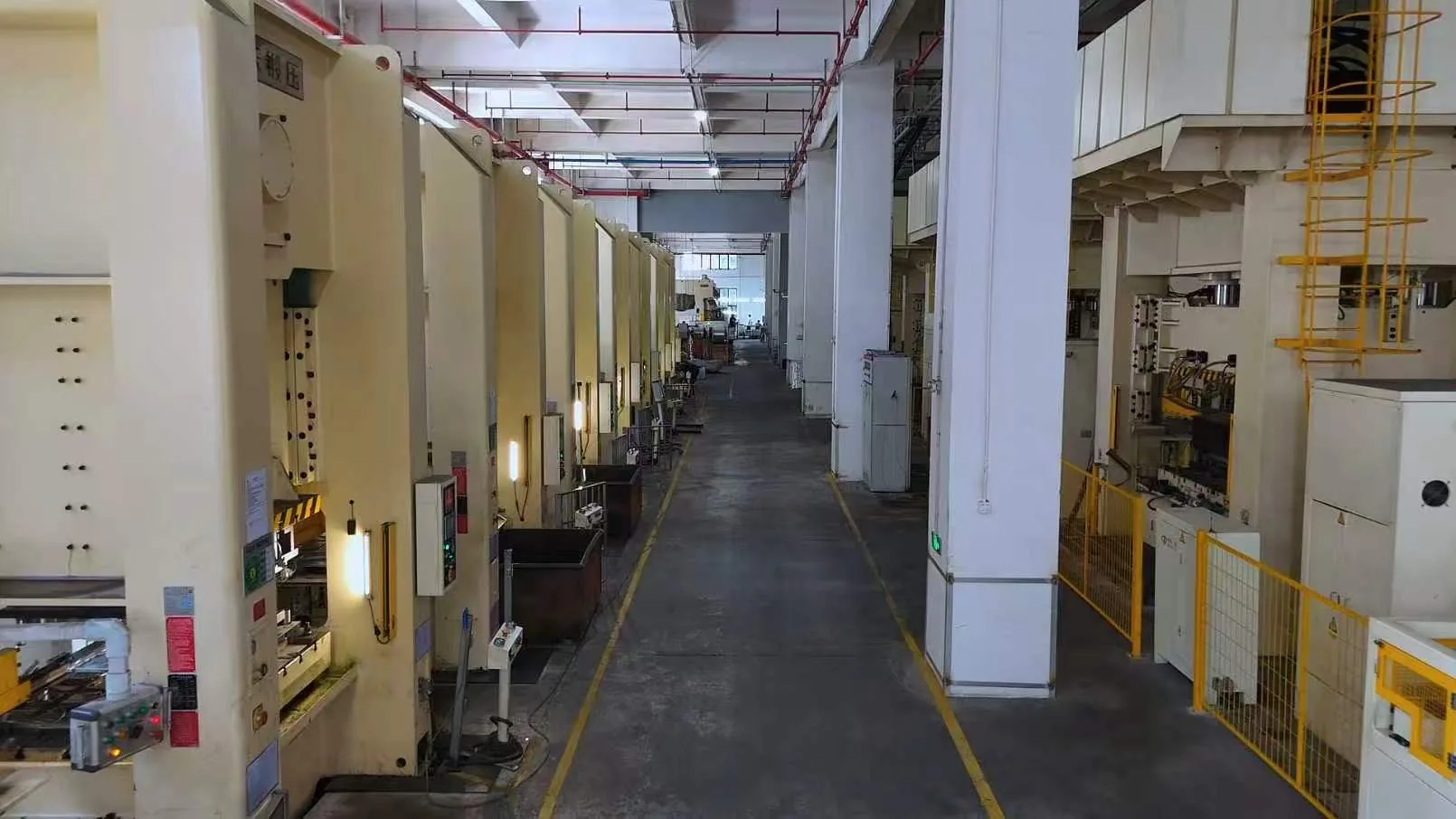
KINGSUN's current public evidence connects metal stamping with tooling, automated feeding and handling, welding, coating coordination, assembly and inspection resources. That is more meaningful than press tonnage alone because it describes a connected manufacturing chain. It still does not mean every TV back plate uses every process. The drawing and approved process plan decide the route.
6. Trial parts are where product intent meets manufacturing reality
A CAD model and tool design describe the intended geometry. Trial parts show what the actual material, tooling, press, feeding conditions and forming sequence produce together. Sample trials are therefore part of production engineering, not just a final checkpoint before mass production.
During trial, the team may review dimensional variation, formed heights, hole position, flange geometry, flatness, appearance, scratches, coating behavior, burrs, local deformation and fit to surrounding parts. If a part does not meet the requirement, the response can involve tool adjustment, process adjustment, clarification of the drawing or—when the product itself remains open—an engineering decision by the customer.
The objective is to establish a process that can repeat the approved result. A supplier should be able to distinguish a one-time acceptable sample from a stable production condition. That distinction becomes more important as the number of interfaces and critical features increases.
Production release should therefore connect sample approval to a known drawing revision, known material, defined process, current tooling status and agreed inspection method. If those records are disconnected, a later batch can reproduce the wrong condition even when the operators follow their local instructions correctly.
Approved drawing revision · controlled material specification · approved tooling/process condition · closed sample issues · defined critical characteristics · agreed inspection method · packaging/handling requirement · documented open deviations, if any.
7. Quality means assembly readiness, not only passing outer dimensions
A TV back plate can pass a simple length-and-width check and still create assembly problems. The features that matter are the ones that control how the part works with the rest of the product. That can include datum relationships, board mounting points, speaker interfaces, connector openings, wall-mount geometry, stand features, formed heights, local flatness and surfaces that contact or align with other parts.
Inspection planning should follow that hierarchy. Incoming material confirmation protects the process from wrong stock. First-piece inspection confirms setup. In-process checks monitor characteristics that can drift. Final inspection verifies the agreed acceptance condition. Fixture or assembly-fit checks can be appropriate when the relationship between features matters more than one isolated dimension.
Appearance and surface quality also need explicit boundaries. A hidden internal surface and a visible rear surface may not share the same cosmetic standard. Coated material may have handling sensitivities that bare sheet does not. Burr or edge requirements should follow the drawing and customer acceptance criteria instead of a vague phrase such as “standard quality.”
Inspection should confirm that the manufactured part still meets the requirements that matter to assembly. It is not only an end-of-line check; it links the approved drawing and process to the part that will actually be delivered.
8. Change control protects the link between engineering and production
Structural programs change. A connector moves, a speaker layout changes, a coating requirement is revised, a sheet thickness is updated or an existing platform is reused for a new model. The risk is not change itself. The risk is allowing a change to affect product, tool and production records differently.
Every material revision should be reviewed for manufacturing impact. A changed hole may require a punch or secondary-operation update. A revised rib or formed depth may affect material flow. A different thickness may affect tooling clearance, forming behavior or inspection expectations. A new finish can affect handling and downstream processing.
The practical control question is: which tools, settings, gauges and documents now belong to the new revision? The answer can include the tool, program settings, work instructions, fixtures, sample records, inspection documents and packaging instructions.
This is also where shared-platform strategies need discipline. A new product can remain within the known boundary of an existing platform, or it can cross the point where repeated adaptation creates more risk than dedicated tooling. Change control gives the project team the information needed to make that decision consciously.
9. Evaluate suppliers by the manufacturing system they can demonstrate
When evaluating a TV structural-component supplier, equipment lists are useful but incomplete. A better review asks how the supplier connects engineering inputs to production evidence.
| Evaluation area | Useful evidence | Why it matters |
|---|---|---|
| Engineering definition | Drawing/revision review, interface questions, open-item tracking | Shows whether manufacturing begins from controlled requirements |
| Material control | Material specification, incoming identification, thickness/surface confirmation | Reduces the risk of producing the right geometry from the wrong stock |
| Tooling | Tool-design/manufacturing capability, trial process, maintenance or modification route | Shows how geometry becomes a repeatable production asset |
| Process integration | Feeding, stamping, handling, secondary operations and finishing coordination | Reveals whether the full route is controlled or fragmented |
| Validation | Trial records, issue closure, sample approval logic | Separates one acceptable sample from a production-ready process |
| Quality | Critical-characteristic plan, fixtures/gauges, in-process and outgoing checks | Connects inspection to assembly function |
| Change control | Revision linkage across tool, process and inspection records | Protects production after engineering changes |
For buyers, this gives a more useful supplier question than press count alone: can the supplier control the transition from the drawing to a repeatable production part?
10. A good RFQ gives the supplier enough information to start correctly
A useful RFQ does not need to be complete in every detail, but it should distinguish confirmed facts from open questions. For a TV metal back plate, the initial package should normally include the latest drawing or sample status, part role, relevant interfaces, material and thickness if confirmed, surface/finish requirement, tooling status, sample and forecast volume, timing and known validation requirements.
If the material is not final, say so. If a feature is still moving, identify it. If an existing tool is expected to be reused, provide available tool records and the previous product context. If the project requires only a bare stamped part rather than a welded or coated assembly, make the scope boundary explicit.
The TV Structural Components RFQ Guide provides a fuller checklist. Its central principle also applies here: a transparent incomplete requirement is more useful than a complete-looking RFQ built on assumptions.
11. How KINGSUN connects the TV structural manufacturing path
For TV structural programs, KINGSUN's published manufacturing scope connects product development, tooling, metal stamping, injection molding where relevant, coating, assembly and quality control. The OEM & ODM process shows how those stages are organized around one project rather than presented as unrelated factory capabilities.
For a metal back plate, that means starting with the drawing and interfaces, confirming material and finish, deciding the tooling route, preparing the stamping and feeding process, validating trial parts, controlling secondary operations, inspecting assembly-relevant characteristics and managing revision changes through production.
KINGSUN currently publishes evidence for seven stamping production lines, press capacity up to 1800T, tooling equipment, automated feeding and handling resources, coating resources, injection molding capacity and integrated manufacturing workshops on the Why KINGSUN page. Those assets support different project routes; they do not imply that every back plate requires the largest press or every available process.
The manufacturing conversation should therefore begin with the product definition rather than the machine list. If the drawing, material, interfaces, volume and timing are clear enough, the relevant tooling and production path can be reviewed against the real program.
12. Sources and evidence boundary
This article combines KINGSUN's published first-party manufacturing information with general sheet-steel background. External references are used only to support general material and fabrication context; they do not establish project-specific KINGSUN material grades, thicknesses, coatings, tooling conditions or customer requirements.
- Nippon Steel — ZINKOTE electrogalvanized steel sheet and strip, including its Guide to Ordering for specification, coating mass, dimensions, surface treatment, oiling, application and fabrication method.
- Nippon Steel — electroplated / pre-coated steel sheet applications, including flat-screen TV back-cover examples.
Engineering boundary: final project material, thickness, surface specification, tool design, press selection, dimensional tolerance, process sequence and validation criteria must follow the approved project documents and production evidence.