
Article Snapshot
What this article covers
A molded TV component must release from its tool and work with the surrounding assembly. Review walls, reinforcement, fastening and tooling interfaces together, then connect each unresolved concern to a design decision and a specific validation question.
- Define the component's actual locating, supporting and fastening functions.
- Review wall transitions, rib intersections and screw bosses as connected geometry.
- Agree draft, texture and permitted tooling-mark locations before tool details are frozen.
- Close DFM issues against the selected resin grade and measurable assembly requirements.
An injection-molded TV structural part can look straightforward in an assembly model while containing difficult decisions at every junction. A screw boss meets a wall, reinforcement crosses behind a visible surface, and a connector opening approaches a locating feature. Reviewing each feature separately misses the relationships that determine whether the molded component can be made consistently and assembled without unwanted stress.
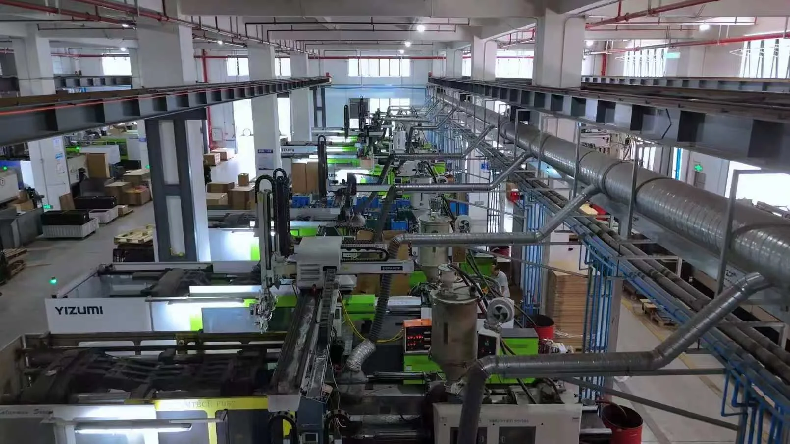
This guide addresses design for manufacturability, or DFM, for molded TV housings, supports and related structural components where applicable. The cover shows the supplied KINGSUN molding workshop, including machines and overhead services; it does not establish a particular part's dimensional capability or test performance. The practical review below requires the actual part model, mating components and engineering requirements.
1. Start with the component's assembly function
Identify what the part actually does before commenting on its thickness. Does it locate a board, enclose the rear assembly, support another component or provide a cosmetic boundary? A single housing can combine these functions, but a molded cover should not be assigned a load-bearing responsibility merely because it contains mounting features. Confirm the intended load path with the product designer.
Mark the surfaces that seat, locate, clamp or remain visible. Add the mating-part revision and the assembly sequence to this map. Distinguish a screw clearance hole from a locating hole, and distinguish a boss that establishes board height from one that only retains a cover. These distinctions guide which features need close dimensional attention and where movement can be accommodated.
General planning table: use these questions to organize a project-specific interface review.
| TV interface | Question to resolve | Information needed | Review owner |
|---|---|---|---|
| Board support | Which features locate and which clamp? | Board revision, seating plane and component envelope | Mechanical design |
| Housing perimeter | Where is the visible gap evaluated? | Mating frame, fastening state and viewing zones | Product design |
| Connector opening | Can the connector be used after assembly? | Plug insertion envelope and board position | Assembly engineering |
| Service access | Must fastening survive repeated opening? | Service requirement and chosen fastening system | Design and service |
2. Review walls and transitions as a continuous section
Nominal wall thickness is only the starting point. Examine sections through perimeter returns, connector pockets, bosses and rib roots. Look for material accumulating where otherwise reasonable features meet. A thin wall beside a large solid junction deserves a different discussion from a broad region with a consistent section. Ask the supplier to mark the actual concern on a sectioned model.
Protolabs' wall-thickness guidance connects uneven sections with sink, warpage and dimensional problems, and describes coring as an alternative to bulky sections. Treat its published ranges as guidance within its manufacturing context. The selected grade, part geometry and tooling proposal must determine the project dimensions.
For each proposed transition, ask what requirement prevents a smoother change or a cored region. A designer may need a seating pad, but the full volume underneath that pad may not be functional. Record the protected seating surface and allow the surrounding geometry to be explored. Keep the minimum required clearance visible when material is removed, especially near wires, board edges and moving assembly tools.
3. Give every rib and gusset a defined job
Start a reinforcement review by naming the behavior to improve: perimeter deflection, local boss movement or handling flexibility, for example. Place proposed ribs on the assembly map and ask how they connect the relevant regions. A dense grid added without a load or deflection question can occupy useful assembly space while creating more intersections to evaluate.
Covestro's Part and Mold Design guide treats rib base thickness, height, spacing, radii and draft as linked design considerations. That supports reviewing the whole rib section rather than adopting a single thickness ratio as a guarantee against sink.
Request views of rib ends and crossings, including the exterior face opposite them. Check whether a gusset reaches a functional support or simply terminates in an unsupported wall. Ask whether the reinforcement blocks a screwdriver, harness route or inspection access. If the supplier recommends reducing a rib, retain the original stiffness question in the issue record so improved moldability does not silently replace the structural requirement.
4. Design bosses around the actual fastening system
A boss review needs the specified screw or insert, the mating stack and the intended assembly process. Record head style, engagement arrangement, access direction and the surface being clamped. Check that the screw can seat before reaching an unintended stop. Also establish whether the boss controls spacing: compressing the surrounding housing to reach a board support is a different condition from clamping a correctly seated stack.
EJOT's DELTA PT technical explanation describes thread geometry developed for direct fastening into plastics and design support that depends on material and pilot-hole dimensions. It reinforces the need to specify the fastening system rather than transfer a screw rule from another resin or joint.
Ask the fastening specialist to review the proposed boss section, pilot hole and engagement for the chosen grade. Agree how assembly development will distinguish seating from stripping, splitting or screw failure. Installation torque, speed and permitted reuse need application evidence; this article supplies no universal torque setting. Include the condition after the required service operations if reopening is part of the product brief.
Keep changes coordinated. Enlarging the outside of a boss, altering its support or changing the pilot hole should trigger a review of adjacent clearance and the corresponding tool detail.
5. Resolve draft and texture before protecting surfaces
Show the proposed mold-opening direction on the model and identify surfaces that release in other directions. A drawing that labels an entire wall as a precision interface may unintentionally constrain the taper needed for release. Ask which height or local contact band actually defines the mating relationship, then evaluate the geometry around that functional location.
Protolabs' molding basics explains that draft reduces drag during release and that insufficient draft can increase ejection demands. Its advice also relates release to surface and tool conditions. Choose the angle with the toolmaker for the actual depth, finish and resin rather than treating a commonly quoted angle as universal.
Define the texture reference and its boundary before completing the release review. Specify where appearance matters, including surfaces visible through openings. Request confirmation that the proposed texture can coexist with the agreed draft and interface. If the answer requires changing the perimeter shape, take that proposal back to product design before committing it to tool steel.
6. Review gates, ejectors and parting lines on the assembly
Request a marked model showing proposed gates, ejector contact zones, parting lines and any side actions. Discuss these locations with the assembly and appearance reviewers together. A mark hidden in an isolated part view can sit directly beneath a board support or at a visible perimeter once the component is installed.
Protolabs' plastic injection-molding design guidelines provide a separate starting reference for mold-related features and limitations. Use the supplier's actual tool proposal to establish where vestiges, witness marks and split surfaces will occur on this TV part.
For each location, agree whether trimming is required, what surface must remain clear and how the resulting condition will be evaluated. Ask the toolmaker to identify predicted flow-front meeting regions and any concerns near loaded fastening features. Record predictions as review inputs requiring confirmation, with the relevant location and rationale attached.
Avoid accepting an unrestricted “non-cosmetic side” designation. The inside of a housing can still contain seating pads, cable paths and service contact points. Mark permitted contact zones explicitly so later tooling adjustments can be reviewed against a useful boundary.
7. Connect shrinkage and warpage to functional fit
Ask how the proposed tool dimensions account for the selected resin and which part relationships are most sensitive to shape change. Covestro's guide includes mold shrinkage, cooling and warpage among the design topics. A single allowance in the tool model does not by itself establish that every interface will meet its requirement.
For a large molded rear component, identify the perimeter gap, board-support relationship and connector alignment separately. Define whether each requirement is evaluated free, supported or fastened, and describe that condition. A housing pulled into position by screws can conceal an unwanted load on another component. Ask the design owner what amount of assembly accommodation is intended.
Plan measurements that answer those specific questions. Record the support points, measurement timing and environmental condition where relevant, together with the mating-part revisions. If prediction software is used, retain its assumptions and the features it is intended to assess. The useful comparison is between the predicted concern and measured behavior in the defined assembly, rather than between an attractive simulation image and an unqualified statement that the part fits.
8. Specify the resin grade behind the geometry
A polymer-family name leaves important decisions unresolved. Request the manufacturer, exact grade, color designation and applicable material documentation. Record any agreed restrictions on substitutions or reclaimed material. Ask the material supplier which grade data and processing instructions apply to the proposed part, including preparation requirements relevant to the molding operation.
Keep the material definition attached to the DFM issue set. If a different grade is proposed, ask which earlier decisions must be reconsidered: filling a long wall, supporting a screw joint, maintaining a perimeter relationship or meeting the product's specified environment. Assign that review before the substitution becomes routine purchasing input.
For any required flame, electrical or other classification, obtain the applicable grade documentation and have the responsible product authority confirm its scope and conditions. A resin-family description or workshop photograph does not establish a finished TV's certification. Likewise, a claim that an alternative is “equivalent” needs defined criteria and an authorized disposition, including what evidence must be repeated.
9. Compare a hypothetical reinforcement tradeoff
Hypothetical design tradeoff, not a KINGSUN project result: suppose a rear housing has a board-support boss beside a visible outer wall. The team wants less movement during fastening, while the mold review flags a heavy junction behind the exterior face. Three proposals deserve evaluation against the same requirements.
| Proposal | Intended benefit | Question introduced | Evidence needed |
|---|---|---|---|
| Increase the local solid section | Support the boss directly | Can the exterior and section be molded acceptably? | Section review and appearance assessment |
| Connect the boss with revised ribs | Support it through another geometry | Do ribs obstruct access or affect neighboring surfaces? | Tool review, clearance and joint evaluation |
| Move the boss and board mounting point | Place support in a different region | Can the board and connector layout change? | Customer layout decision and interface recheck |
No option wins from its sketch alone. The assembly owner confirms the allowable board movement and access; the toolmaker reviews the sections; the appearance owner defines the visible acceptance condition. If the board mounting point is fixed, close that option with a reason rather than leaving it in circulation. Select the next proposal using an agreed evaluation, keeping the original geometry and decision history available.
10. Close DFM issues with disposition and focused validation
Give each concern an identifier, marked feature, affected revision, consequence and decision owner. Separate a question awaiting product definition from a supplier geometry proposal. Suitable dispositions include revise the part, revise the tool proposal, retain the design with a defined evaluation, or request missing information. “Discussed” does not identify the next permitted action.
Attach closure evidence to the issue. For a rib change, that may include an updated section and the corresponding support requirement. For a boss change, include the approved fastening definition and the planned joint evaluation. For a gate relocation, confirm both the tool drawing and the permitted mark zone. Check that the resulting CAD, drawing notes and tool inputs describe the same decision.
Validate the uncertainty that justified the change. Evaluate the affected assembly clearance, fastening behavior or appearance region using the agreed setup and identifiable molded parts. Record material grade and relevant tool configuration so an observation can be traced to the configuration tested. Define acceptance criteria before examining the result, and return unexplained failures to the issue owner.
This closes the design-review loop without replacing the broader tooling-trial and sample-approval process. The handoff should tell that process which risks remain, which evidence is required and which interfaces must be protected during further adjustment. KINGSUN's injection-molding scope provides the manufacturing context; feasibility remains subject to the controlled project package.
11. Sources and engineering boundaries
The following primary manufacturer references support the general molding and fastening background. The TV interface questions, tables and hypothetical tradeoff are planning guidance, with no claimed customer result, universal dimensional limit or KINGSUN process qualification.