
Article Snapshot
What this article covers
A useful TV structural-part inspection plan translates controlled assembly requirements into a traceable set of measurements, observations and release decisions. It distinguishes what can be checked from what requires explicit engineering approval.
- Why assembly interfaces, rather than an undifferentiated list of dimensions, should define inspection priorities.
- How drawing revision, material identity, datums and fixture conditions establish a reproducible baseline.
- What first-article, dimensional, edge, surface and assembly-fit checks can reveal.
- How measurement traceability and inspection sampling support trustworthy decisions.
- Which quality records and unresolved acceptance criteria a buyer should request before production release.
A TV structural component may pass a casual visual check and still create a difficult assembly problem. An offset board-mounting hole, a distorted formed edge or a burr facing a cable can matter more than a nonfunctional dimension that happens to be easy to measure. Reliable quality evaluation therefore connects part definition, the inspection setup and the final assembly requirement.
Buyers and suppliers need to share more than a pass/fail spreadsheet. They need a controlled drawing revision, a material and process context, a defined datum scheme, appropriate inspection methods, agreed acceptance criteria and a response when the measured result falls outside the requirement. This guide explains how to organize those decisions without pretending that one universal TV inspection tolerance or sampling rate exists.
1. Inspect the assembly requirement, not only the loose part
Inspection of a TV structural component begins with a product question: what must this part locate, support, protect or connect when the television is assembled? A back plate can appear acceptable on a table yet create difficulties when a board, speaker, panel module, stand bracket or rear cover is fitted. Conversely, a cosmetic difference that has no agreed functional consequence may not deserve the same control effort as an inaccessible mounting feature. The inspection plan therefore needs an assembly-level definition before an inspector selects a gauge.
For a stamped back plate, the checks may involve hole patterns, formed features, overall profile, flatness in a specified setup, locating edges, burr direction and surface damage. For a molded housing, the relevant concerns may include boss position, rib condition, mating edges, warpage, ejection marks and appearance surfaces. These are possible inspection categories, not a declaration that every KINGSUN project uses the same checklist. The approved drawing, sample agreement and customer acceptance conditions determine the actual scope.
A useful review identifies each critical-to-function feature, the downstream part it mates with and the failure mode if the feature drifts. That moves the conversation from “please inspect everything” to a practical, risk-weighted control plan.
2. Establish an unambiguous inspection baseline
Before measurements start, the supplier and buyer should agree on the authoritative document set. At a minimum, this means the part number, drawing revision, applicable 3D geometry, material and finish specification, approved reference sample if one exists, and the intended assembly context. When the tooling revision differs from the drawing revision, the mismatch must be resolved instead of silently choosing the version that is easier to measure.
Classification also matters. The team should distinguish critical assembly interfaces from general dimensions, functional edges from visible cosmetic faces, and customer-specified inspection characteristics from useful internal process checks. A hole used for temporary handling has a different risk profile from a datum-related hole that fixes the circuit-board position. An oversimplified “all dimensions are equally critical” policy can waste inspection effort while missing the features that drive assembly failures.
Capture any agreed measurement conditions: free state or fixture-constrained state, temperature where relevant, datum support, orientation, coating state and whether dimensions are checked before or after secondary processes. Otherwise two valid-looking reports may disagree because they measured different physical conditions rather than because the parts differ.
3. Review material and incoming condition first
Inspection does not begin only after stamping. The material entering production affects the geometry and surface condition that can be achieved. A review may require confirmation of sheet designation, nominal thickness, coating and surface condition against the controlled purchase specification. For a galvanized sheet, the name of a grade alone is not a complete order or acceptance specification; the details belong to the approved material package.
Incoming checks should follow the risks identified for the actual program. Teams may review supplier certificates, identification and lot traceability, thickness at agreed locations, obvious transit damage, corrosion, surface contamination or mixing between material batches. A certificate is evidence about material identity and stated properties, not a substitute for verifying whether the delivered material matches the specific drawing and purchasing agreement.
If material changes, the impact may extend beyond an incoming inspection form. Thickness and forming behavior can affect die clearance, springback, hole quality, assembled height and post-process appearance. Record the proposed change and its approval status so a production inspector is not left to make an engineering substitution decision at the line.
Related reading: SGCC material confirmation for TV metal back plates explains why grade, thickness, coating and surface treatment require separate confirmation.
4. Use first-article inspection to confirm the manufacturing setup
The first-article review should compare an initial part or agreed sample set against the current controlled requirements. It can reveal missing drawing assumptions before volume production amplifies them. The review is especially important when a new die, modified tool, transferred tool, revised material, changed secondary process or major setup change is introduced.
Plan the measurement sequence deliberately. First identify the specified datum references and fixturing condition. Next verify the dimensions and geometric relationships most likely to affect assembly. Then assess forming quality, edges, surface condition and any customer-agreed functional checks. Log the actual measured results, not only an “OK” conclusion. An annotated drawing or characteristic list helps the receiving team reconcile a report with its revision.
First-article approval does not automatically prove stable mass production. It shows that a defined setup produced parts meeting the reviewed criteria at that checkpoint. Repeatability still depends on the ongoing process, tooling wear, material variation, handling and inspection frequency. If the first article fails, distinguish a drawing interpretation issue from a tooling, setup, material or measurement-system problem before changing the process.
5. Measure positions, profiles and flatness against defined datums
TV structural components contain many features that matter because of their relationships. Hole diameter may be acceptable while the hole pattern is displaced relative to the panel-side datum. A mounting feature may have an individually correct height while the overall profile clashes with the rear housing. Inspection should therefore follow the dimensional and geometrical scheme on the drawing, including the specified datums rather than arbitrary convenient edges.
ISO 1101 provides a standardized language for geometric characteristics such as form, orientation, location and run-out. It does not supply universal TV-back-plate tolerances. Those limits, datum definitions and acceptance rules must be specified for the actual part. Engineers should also identify whether the inspection method can reproduce the same reference setup used by the designer and assembly fixture.
Potential characteristics include local form, overall bow or twist, edge-to-hole position, mounting-feature height, connector cutout position and mating-surface clearance. Flatness deserves special care: a thin sheet may flex under its own weight or fixture forces, so a free-state reading and an assembly-constrained reading are not interchangeable. The report should state which condition was evaluated and why it represents the product requirement.
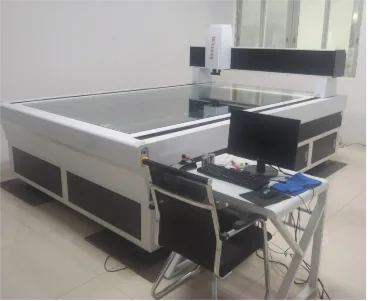
For thin or complex parts, a coordinate measurement, optical system, appropriate gauges or a designed checking fixture may be useful. The correct tool is the one that evaluates the agreed characteristic with adequate capability; buying the most advanced instrument is not itself a quality plan.
6. Evaluate edges, forming defects and surface requirements
A drawing may control size and position yet say little about what happens during handling or assembly. Stamped edges can carry burrs; formed corners can show cracking or local thinning; handling can damage a visible or coated surface. Those conditions deserve explicit acceptance criteria where they affect worker safety, assembly, electrical clearance, corrosion performance or visible quality.
Burr orientation can matter as much as a measured burr height when an edge faces a cable, gasket, molded part or assembly operator. A method for inspecting burrs should state where to check, whether an edge-break requirement exists, the permitted observation method and the response to nonconforming areas. Avoid a universal numerical burr limit without a customer specification.
Surface checks should distinguish functional contact zones, concealed engineering surfaces and visible cosmetic areas. For coated components, identify whether marks are evaluated before or after coating and whether coverage or adhesion testing has been separately specified. Photographs can support defect classification, but lighting, scale and viewing distance should be consistent if photos are used to make acceptance decisions.
A practical defect register includes the observation, location, suspected cause, containment action and whether the finding requires engineering approval. It should not silently transform a one-time exception into a permanent undocumented acceptance standard.
7. Validate the actual interfaces and assembly sequence
Dimensional results are necessary but may not be sufficient. Where parts have several interacting interfaces, trial assembly against an approved mating component or master fixture can uncover interference, orientation errors, fastener-access problems and cumulative stack-up effects. The test needs a documented fixture or counterpart revision; otherwise a changed mating component may wrongly be blamed on the inspected part.
Typical TV structure questions include whether the board mounting locations align, whether speaker or connector openings clear their neighbors, whether the stand or wall-mount region engages correctly, and whether the rear housing sits without unacceptable gaps or stress. Cable routing, ventilation openings and the intended order of fastening may also be relevant. Which features are applicable depends on the product architecture.
Do not claim that a single assembled sample proves every durability or regulatory requirement. Fit verification demonstrates fit under the tested conditions. Additional mechanical, thermal, electrical, vibration or safety evaluation belongs to the program's defined validation scope and competent responsible team. If a risk is out of scope for a supplier's inspection, record that boundary and the party responsible for closing it.
8. Make measurement evidence reproducible
A report is only useful when another qualified person can understand how the result was obtained. Specify the measuring instrument or fixture, the part support condition, reference datums, measurement locations, operator or responsible role, sample identification and drawing revision. For important measurements, define calibration status, applicable uncertainty considerations and whether the system is capable of differentiating an acceptable part from one close to the tolerance boundary.
NIST explains metrological traceability in terms of an unbroken calibration chain to a stated reference and the measurement result's associated uncertainty. This is a measurement principle, not evidence that any specific supplier instrument is calibrated. Buyers should request records appropriate to their critical characteristics instead of assuming that all readings with several decimal places are equally reliable.
Fixture repeatability, operator technique, contact force, coating thickness and temperature can influence some dimensional results. A borderline reading should trigger a review of the measurement method and decision rule before a team declares the part good or bad based on the last digit displayed. Where applicable, the customer and supplier can agree on a measurement-system study or repeat-check protocol.
9. Separate process control from final lot acceptance
An approved first article establishes a starting point. During production, a control plan should detect changes early enough to limit suspect material. Checks may be triggered by startup, tool adjustments, material-batch changes, maintenance, shift changes or defined production intervals. The frequency must come from risk, process performance and customer requirements rather than a generic promise to inspect every tenth or hundredth item.
In-process checkpoints may focus on hole location, forming height, burr condition, flatness, surface protection or tool-related wear indicators. Record nonconformities with affected-lot identification so containment is traceable. When a drift appears, the response should include isolating potentially affected parts, correcting the process and deciding what reinspection or customer authorization is necessary.
Lot acceptance is a different question. ISO 2859-1:2026 describes acceptance-sampling systems indexed by acceptance quality limit for inspection by attributes. It does not impose one AQL value, sample size or acceptance number on a TV back plate. Those choices, when appropriate, must be agreed within the customer quality framework. Critical safety or assembly interfaces may need different controls from ordinary visual features.
Sampling also cannot compensate for an unstable or poorly defined manufacturing process. A sound arrangement connects incoming checks, first-article evidence, in-process control and final acceptance into one traceable record.
10. Example inspection decision matrix
The matrix below is a planning aid for procurement and engineering discussions. It is deliberately qualitative: limits and frequencies cannot be specified responsibly without the approved product documents.
| Characteristic | Failure to prevent | Possible evidence | Project-specific decision |
|---|---|---|---|
| Datum-related mounting holes | Board or bracket misalignment | Dimensional report against drawing datums | Datum scheme, tolerance, sample plan |
| Profile and formed height | Housing or panel interference | Fixture or coordinate measurement | Support state, acceptance limits |
| Flatness or distortion | Assembly stress and uneven seating | Defined free-state or constrained evaluation | Fixture loading and functional requirement |
| Cut edges and burrs | Handling, cable or mating-surface damage | Edge condition review at identified zones | Limits, directions, inspection method |
| Surface or coating condition | Cosmetic or protection nonconformance | Agreed visual or specified surface test | Viewing rule, protected zones, finish requirement |
| Assembled interfaces | Fit, access or fastening problems | Master fixture or mating-part trial | Revision, setup, functional acceptance |
The most useful output of this exercise is not the table itself; it is the list of unresolved decisions. If the buyer has not identified an authoritative datum or a surface acceptance rule, the supplier should request clarification rather than inventing one to complete a report.
11. What a buyer should request before production release
A practical supplier review package should identify the responsible engineering contact, part and drawing revision, material evidence, agreed critical characteristics, measurement instructions, initial-sample results, any open deviations and their written dispositions, relevant assembly-fit evidence, and a plan for lot traceability. Depending on the program, it may also include fixture identification, gauge checks, process-change notification rules and customer sign-off.
Before accepting a report, ask whether every important finding can be traced back to the corresponding drawing requirement. Confirm that failing measurements have a disposition rather than being silently dropped. Verify that an approved sample remains associated with the current tool, material and revision; a sample from an obsolete revision should not become the default acceptance authority.
For early-stage projects, do not demand finalized production documents before the design itself is defined. Instead divide the RFQ into confirmed requirements and open decisions, then determine which samples, fixtures or tests are needed to close the gaps. This keeps the quality discussion connected to engineering maturity and commercial timing.
KINGSUN describes its relevant metal stamping, tooling and OEM/ODM coordination capabilities in the linked site sections. Those capabilities are a starting point for discussing a program-specific inspection approach; they are not a claim that an unreviewed part has already passed testing. The TV structural-component RFQ guide provides the broader input checklist.
12. Sources and engineering boundaries
This is a general engineering and sourcing guide grounded in KINGSUN's published manufacturing scope. It does not publish a factory-specific inspection report, customer result, calibration certificate, tolerance value or certification claim. The following external references support the measurement and sampling concepts rather than validating any particular KINGSUN process.
- ISO 1101:2017 — Geometrical product specifications and geometrical tolerancing.
- ISO 2859-1:2026 — Acceptance sampling by attributes.
- NIST — Metrological traceability questions and answers.
Engineering boundary: acceptance criteria, inspection equipment, gauge capability, sampling arrangements, compliance obligations and release decisions must be agreed against the current drawing and the applicable customer quality specification.