
Article Snapshot
What this article covers
Before tooling or quotation can be confirmed, the drawing package must identify the actual part, its controlling revision and the interfaces that matter to the TV assembly. This guide shows how to turn mixed drawings, CAD files and samples into a clear engineering review package with explicit decisions and owners.
- Establish authority and revision consistency across drawings, CAD and reference samples.
- Define datums and interfaces from the actual assembly requirements.
- Turn manufacturing concerns and file discrepancies into questions with accountable owners.
- Assess the impact of changes and prepare a controlled review handoff.
Having a drawing does not mean that a TV back plate is ready for manufacturing review. A sourcing team may receive an assembled-TV outline, a detailed model, a PDF with handwritten comments and a sample from an earlier development round. Each contains useful information, but the combination can leave uncertainty about the part being ordered. A supplier cannot reliably resolve that uncertainty by choosing whichever document appears most complete.
A good drawing review creates a shared product definition before detailed tooling decisions begin. It identifies the controlling requirements, the mating parts, the reference conditions and the open decisions. The result should let another engineer understand what has been agreed without reconstructing a long email conversation. This guide focuses on that definition and handoff; measurement methods and production acceptance belong to the subsequent inspection and approval plans.
1. Define the part and the authority of each file
Start with a precise part identity. Confirm whether the request concerns a metal back plate alone, a structural kit or an assembly that includes other components. Record the customer part number and distinguish it from a commercial TV model name. Similar product names can cover several board layouts, connector locations or rear-housing configurations, so a screen size or photograph is insufficient identification.
Assign a purpose to each supplied item. An assembled-TV six-view reference can explain external layout; a production drawing can define requirements; a three-dimensional model can describe geometry; and a physical sample can communicate an agreed surface or assembly condition. The project must explicitly decide which document controls each requirement and what happens when documents disagree. Neither PDF nor CAD has automatic priority across every program.
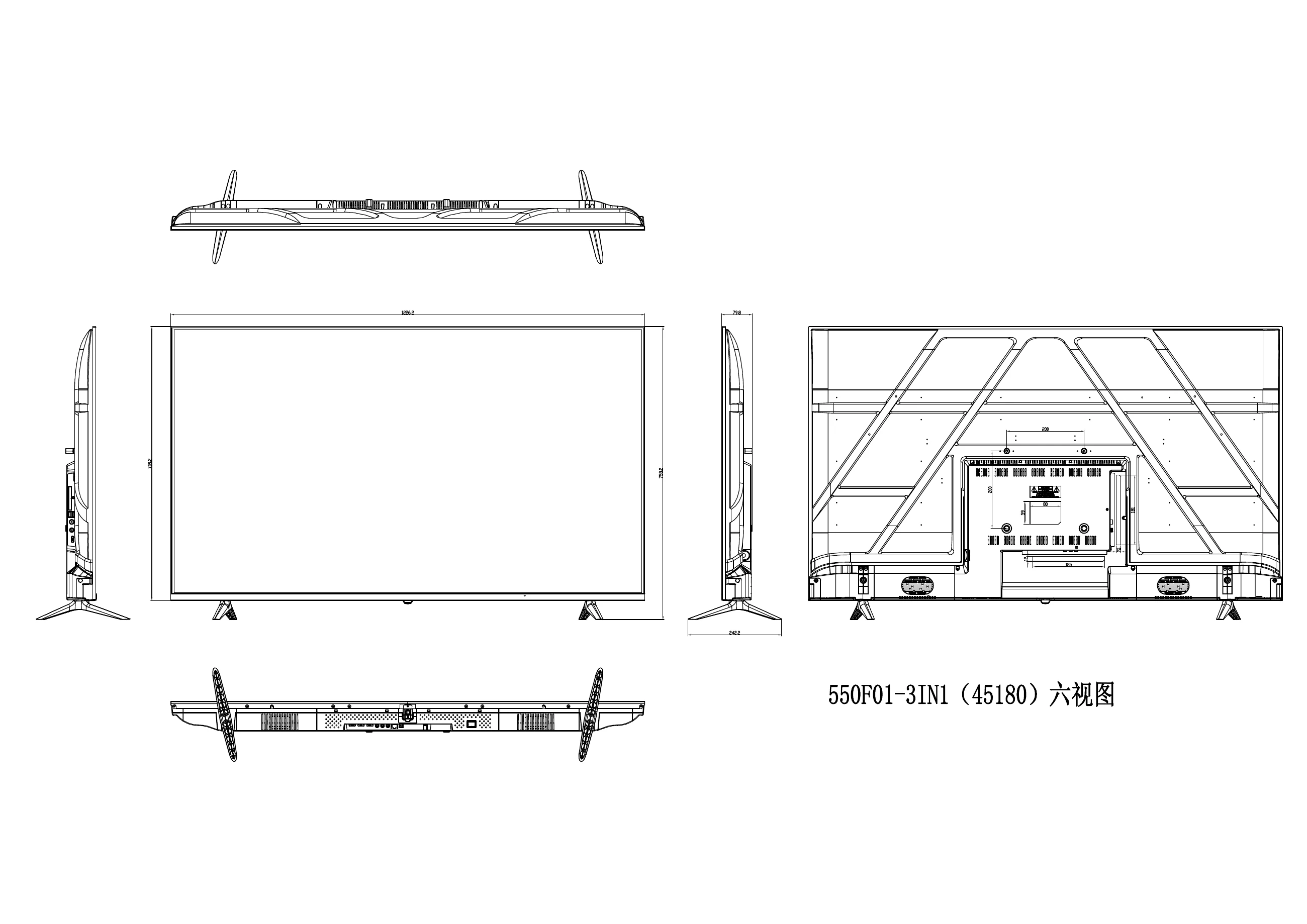
The image above is the supplied 550F01 3IN1 assembled-TV reference. It helps identify the product context, but it does not establish a complete back-plate production specification. Request the actual part drawing and applicable revisions before using an external view to infer hole positions, material notes or assembly clearances.
2. Establish one controlled drawing package
Create a file register before reviewing individual dimensions. For each item, include the part number, exact document name, revision, units, release status, issue date and responsible owner. Identify linked specifications and mating-part drawings as well as the main part files. A revised model accompanied by an obsolete drawing is an unresolved package, even if the revised model opens successfully.
Use a named package issue or transmittal so both teams can refer to the same collection. Superseded documents should remain retrievable for change history while being clearly separated from current manufacturing input. Where filenames lack revision information, document the identification method rather than asking production personnel to infer status from file timestamps.
Configuration management has an established background: ISO 10007:2017 provides guidance applicable through the product and service lifecycle. The register proposed here is a general planning aid, not a claim that the standard mandates this exact format. Its practical purpose is to prevent a quotation, tool review or sample order from advancing against an ambiguous baseline.
3. Identify functional datums before reviewing dimensions
A datum scheme describes the references used to establish the part's relevant geometric relationships. Discuss how the back plate is located in the intended assembly: which surface seats first, which feature locates it and what prevents the remaining movement? Then check that the drawing communicates those references clearly. An easily accessible edge is not necessarily the edge that controls the board or housing position.
The customer should identify the applicable drawing convention. ISO 5459:2024 addresses datums and datum systems in geometrical product specification, while ASME Y14.5 covers dimensioning and tolerancing conventions including GD&T. These references support the need for a defined language; their rules should not be casually mixed within a review.
For a flexible stamped component, also ask whether a requirement applies in the free state or under specified assembly restraint. Record the intended support and fastening context where it affects interpretation. Do not select numerical tolerances or fixture forces during a sourcing discussion merely to fill blank fields; return those design decisions to the responsible engineer.
4. Build an interface map for the actual TV assembly
List the parts that actually interact with this back plate. Depending on the architecture, they may include a display module, circuit boards, connectors, speakers, a molded rear housing or a support bracket. Some interfaces belong to separate structures rather than the back plate. Confirm applicability instead of importing a generic television checklist into every program.
For each applicable interface, connect the mating-part revision to the relevant drawing reference and functional requirement. Board mounting involves more than a hole pattern: the resulting board position can affect connector clearance and access for assembly. A connector opening may require space for insertion and removal as well as clearance around the installed connector. A housing interface may depend on fastening order and the intended assembled state.
General planning example: use an interface confirmation table to expose missing decisions. Entries below illustrate questions; they do not define a KINGSUN product or approved customer assembly.
| Interface | Mating part and revision | Controlling reference | Functional requirement | Open decision and owner |
|---|---|---|---|---|
| Board mounting | Customer board, current revision | Drawing datum and hole pattern | Locate board for the agreed assembly | Confirm fastener specification; customer mechanical engineer |
| Connector opening | Board and rear housing revisions | Opening detail and assembly layout | Provide agreed access and clearance | Confirm insertion envelope; customer assembly owner |
| Housing engagement | Rear housing, current revision | Mating-edge detail | Seat in the defined fastening state | Confirm gap requirement; product engineer |
| Bracket region, if applicable | Approved bracket drawing | Interface drawing | Meet the specified engagement requirement | Assign validation responsibility; customer design owner |
5. Separate form, position and assembled-fit requirements
A local size, a feature position and an assembled fit answer different questions. An opening width can match its nominal dimension while the opening is displaced relative to the board. A formed region can meet a local height requirement while the surrounding plate shape causes interference. Review relationships separately so a dimension list does not hide an incomplete assembly definition.
Ask the designer to identify where local geometry matters, where datum-related position matters and where a complete assembly evaluation is required. If flatness or profile is specified, confirm the relevant region and part condition. If a gap is specified between two assembled components, identify both revisions and the setup in which that gap is evaluated.
Overall TV dimensions cannot establish these requirements. Likewise, a loose sample that fits by hand does not define the permitted variation for future parts. A reference sample can support interpretation only within its documented role. Translate subjective comments such as “fits well” into an explicit question about seating, interference, access or the agreed appearance condition.
6. Review manufacturing-sensitive features as questions
Use the product definition to open a focused discussion about manufacturability. Review holes near formed regions, narrow sections, flanges, reinforcing features, cut edges and areas requiring tool access. Ask which features can be created and inspected in the proposed sequence, which may move during forming and whether secondary operations change the intended reference condition.
For example, a feature added for board clearance may also alter support during forming. A flange may restrict access to a mounting fastener or an inspection probe. A formed rib can interact with an adjacent part even when its purpose is structural. These observations are reasons to request engineering review, not reasons to apply an invented universal hole-to-edge distance or bending radius.
Separate a supplier proposal from an approved design change. Record the proposed geometry, its manufacturing rationale and the interfaces that require reassessment. The customer should decide whether the change preserves product intent. KINGSUN's metal stamping scope provides context for this discussion, while feasibility and tool details still require review of the actual controlled part.
7. Connect material and finish notes to the same revision
Material and finish requirements belong in the controlled package because they can affect forming, interface height, surface acceptance and handling. Check that designation, thickness, coating and any additional finish notes refer to the same revision as the geometry. A procurement description copied from an older order should not silently override the current drawing.
Identify protected surfaces, permitted contact zones and areas where coating or surface condition matters to assembly. Clarify whether the requirement applies before or after secondary finishing. The SGCC material guide explains the separate material inputs in more detail. Here the essential decision is whether those inputs are complete, consistent and approved, including the process for evaluating a proposed substitution.
8. Resolve discrepancies between CAD, drawings and samples
Illustrative general planning example: suppose the three-dimensional model shows a connector opening in one location while the PDF shows it closer to a mounting feature. A supplied sample resembles the PDF, but its identification label does not show the revision. The team has a discrepancy, not evidence that one representation is automatically correct.
Log the affected feature, each document revision, the observed difference and the possible assembly consequence. Request a decision from the design authority with the relevant board and housing references attached. Keep the manufacturing question distinct from the design question: the supplier may explain tooling implications, but that explanation does not establish the intended connector location.
Once the decision is made, update the controlling documents and issue a replacement package. Link the discrepancy record to that revision and identify which quotations, tool reviews or sample requests need reconsideration. An email can document the discussion, but a casual “use the newer one” should not leave contradictory files in the production package. If a temporary deviation is authorized, specify its scope and expiry rather than presenting it as a permanent revision.
9. Classify changes by their manufacturing impact
A new revision number does not by itself mean a new tool is required. An annotation correction, hole relocation, formed-feature change and material substitution can have very different effects. Compare the actual change to the previous approved baseline and identify the tool, process, inspection and assembly evidence that may be affected.
General planning example: the following impact register helps route questions to the appropriate reviewers. Each disposition must follow the actual program requirements.
| Change | Affected tool or process | Required review | Sample or inspection impact | Approval record |
|---|---|---|---|---|
| Clarified note | Confirm whether requirements changed | Design interpretation | Update characteristic instructions if needed | Current package issue |
| Moved mounting hole | Piercing and related locating features | Tool and mating-part review | Recheck affected interfaces | Authorized revision and review outcome |
| Changed formed region | Forming and support sequence | Tool feasibility and assembly review | Assess new sample requirements | Defined validation disposition |
| Changed finish | Finishing and handling | Material, appearance and packing review | Update applicable acceptance evidence | Customer finish approval |
Include packaging when a change introduces a sensitive surface or a different stacking contact. Assign an owner to every affected activity, so a corrected drawing does not leave an obsolete inspection or packing instruction downstream.
10. Use a drawing-review handoff checklist
A review handoff should state the maturity of the package. “Ready for detailed review” means the input set can be examined coherently; “clarification required” means defined questions remain; “ready to submit for tool review” means the relevant product-definition questions have been resolved. None of these statuses independently grants production approval.
General planning example: summarize the version handoff in a compact register and attach the interface map rather than repeating every dimension.
| Handoff item | Required confirmation | Evidence or action |
|---|---|---|
| Part and file set | Identity, units, authority and current revisions | Issued document register |
| Interfaces | Applicable counterparts and functional requirements | Reviewed interface map |
| Material and finish | Consistent requirements and protected zones | Controlled notes and specifications |
| Open questions | Decision owner, impact and next checkpoint | Issue log with dispositions |
| Next review status | Permitted next activity and remaining limits | Named approval or clarification record |
Before transmitting the package, ask someone outside the original discussion to identify the current part and locate an unresolved interface decision. If that requires personal knowledge, improve the register or issue record. Preserve the package identity when it moves into quotation, tooling and samples so later teams can connect their evidence to the same requirements.
11. Sources and engineering boundaries
These official references support the datum, drawing-language and configuration-management background. They do not supply project-specific TV back-plate tolerances. The tables and scenarios are general planning examples, with no claimed customer result or KINGSUN tolerance specification.
- ISO 5459:2024 — Datums and datum systems.
- ASME Y14.5 — Dimensioning and Tolerancing.
- ISO 10007:2017 — Configuration management guidance.
The customer defines the applicable convention, limits and design authority; detailed standard requirements belong in the controlled project specification. Use the structural-component inspection guide to develop subsequent checks and the RFQ guide to connect the reviewed package to the broader sourcing request.