
Article Snapshot
What this article covers
Thickness is the most visible number on a back plate drawing and one of the weakest predictors of how the part will behave. This guide separates load path, section stiffness, stiffening features and forming limits so a metal thickness decision can be defended and inspected.
- Identify what the panel must resist before choosing a gauge.
- Treat thickness, ribs, beads and flanges as one section problem.
- Recognize that a stronger steel grade does not make a part stiffer.
- Confirm forming, flatness and assembly consequences before release.
A customer message that says "make it a little thicker" usually arrives after a real observation: a panel that flexes when a hand presses the center, a mounting area that distorts under screw torque, or a back cover that hums against a speaker. Thickness is an easy variable to name and a difficult one to prove, because the same increase that fixes one symptom can add mass, worsen springback, change flatness and force a new coil, die adjustment and validation cycle.
This guide treats metal thickness as an outcome of a structural review rather than a starting assumption. It stays inside the structural layer: how load enters the panel, how the section resists it, what the stiffening features actually do, and how the requirement should appear on a controlled drawing. Numerical examples are hypothetical planning illustrations, not KINGSUN design limits.
1. Start with the load path, not the gauge number
Before any thickness can be judged, the panel needs a description of what acts on it and where that action goes. A TV back plate carries its own weight, supports brackets, boards and cable clips, resists handling during assembly and transport, and provides a surface that must not rattle or oil-can in service. Each load enters at a specific location and leaves through a specific attachment.
Write the load path down in plain language. A wall-mount interface transfers load into the panel around a few fasteners, which then spread it toward the outer flange and cabinet. A stand interface concentrates load low and central. A board standoff creates a local pull at each screw. A speaker bracket adds a small vibrating mass with its own frequency. These are different problems and do not respond to the same fix.
The output of this step is a short list of load cases with a location, a direction and an acceptable response. "The center must not deflect noticeably when pressed during assembly" is usable because it names a place and an action. "The part must be stiff" is not, because it cannot be tested or quoted. Ask the owner of the assembly requirement which deflection is unacceptable, and record the answer next to the case.
2. Bending stiffness follows the section, not thickness alone
For a thin plate bending about one axis, the elastic resistance is governed by the material's elastic modulus and by the second moment of area of the section. Thickness enters that relationship cubed, which is why a small gauge change can feel dramatic: raising thickness by roughly a quarter can raise bending stiffness by close to a factor of two. The same exponent works in reverse, and it is why a down-gauge proposal deserves a real calculation instead of a guess.
The correction is that a flat sheet is a poor section. Most of the bending resistance in a well-designed back plate comes from geometry that moves material away from the neutral surface: a return flange at the perimeter, a drawn or embossed bead, a channel-shaped rib, or a folded edge around an opening. Depth in those features raises the second moment of area far more efficiently than thickness across the whole panel, because the working material sits where bending stress is highest.
Elastic modulus is a property of the material family, not of its strength grade. Moving from commercial-quality galvanized sheet to a higher-yield grade changes where the material yields and how much load it carries before permanent set, but it does not make the panel meaningfully stiffer in normal service. Buyers sometimes assume a stronger steel allows a thinner part at equal stiffness; for deflection-limited behavior that reasoning fails, producing a panel that passes a strength check and still feels soft.
3. Map how the panel is actually supported in the TV
A back plate is never a plate on four simple supports. It is fastened at some points, rests against the rear housing at others, carries a stand or wall bracket through a local reinforcement, and is interrupted by openings. The real boundary conditions are irregular, and they change the deflected shape.
Build a support map from the assembly model or a physical build. Mark every screw, clip, locating tab and contact pad, and note whether each restrains translation only or also rotation. Then mark the spans. A long unsupported span behaves very differently from a short one, and one clip in the middle of the longest span can do more than extra gauge across the whole part.
Include the parts that are not obviously structural. Foam pads, cable routing and the rear housing itself may contact the panel and change how it vibrates or deflects. A design analyzed as free at the edges but actually held by a housing rib is misjudged in both directions: over-designed in one region, under-designed in another.
4. Give every rib, bead and flange a defined job
Stiffening features are often copied from a previous model without a stated purpose, and that is how a panel accumulates shapes that cost tooling time but do not carry load. Each feature should have a named function: spread load between fasteners, stiffen a span, protect an opening edge, locate a mating part, provide a flat land for a label, or resist handling damage. If nobody can state the function, the feature is a candidate for removal.
Rib and bead effectiveness depends on depth, width, spacing and end conditions, not just presence. A shallow bead in a wide panel adds little; a deep narrow rib ending mid-span can create a stress concentration and a visible read-through on the cosmetic face. Automotive studies of stiffening methods make the general point that benefit depends on feature proportions relative to the sheet, and that beads need enough depth relative to thickness to work. That is mechanics background from another industry, not a rule for television parts.
Perimeter flanges deserve attention because they do double duty: they stiffen the edge and provide the surface that seats against the rear housing. Too shallow, and the edge bends; too deep, and it interferes with the housing or the assembly sequence. Flange height, bend radius and the number of joggles or relief cuts belong in the same review as the thickness decision.
5. Check forming limits before increasing feature depth
The structural answer and the manufacturable answer are not always the same. Deepening a bead or tightening a bend radius raises section stiffness, but it also raises strain, increases springback and narrows the process window. For galvanized sheet the coating adds another constraint: severe deformation can damage the zinc layer and create a cosmetic or corrosion concern that a bare-steel analysis would miss.
Review the forming sequence before committing to a feature. Ask which operation forms the bead, whether material must flow around a tight corner, and whether the blank leaves enough material for the draw. Ask about bend radius relative to thickness and bend direction relative to rolling direction. These standard questions become decisive when the structural fix sits in one small area.
Springback belongs in the same conversation. A deeper, more highly strained feature stores more elastic energy, so it may open or twist after the tool releases. That appears as flatness loss or a flange angle that no longer matches the housing. If the stiffness fix depends on a feature that cannot be held within tolerance, the design has traded one problem for another. A trial forming run on the intended material is the honest way to find out, and it should precede drawing release.
6. Balance stiffness against mass, flatness and assembly
Thickness is not free. Every additional tenth of a millimeter adds mass across the whole panel, increases coil consumption, raises press load and may require different handling. On a large television back plate the mass difference is small in absolute terms but still matters for packaging, shipping weight and the load on the stand or wall bracket. Down-gauging is usually proposed for exactly those reasons, so the trade must be evaluated rather than rejected.
Flatness is the second constraint. Thicker sheet resists handling and assembly distortion better in some cases, but it also increases forming load and can change the residual stress pattern. A panel that is stiff in the flat state can still bow when flanges are formed or when the part leaves the die. Flatness therefore needs to be stated in the same review as stiffness, because a fix that improves one can degrade the other.
Assembly is the third. Screw torque, clip engagement force, connector insertion force and cable pull all act on the panel. A thinner panel may need a local doubler, a formed boss or a larger washer area, and those features can cost more tooling time than a small gauge increase. The comparison is not "thickness versus nothing"; it is "uniform thickness versus local reinforcement versus section change," each with its own cost and risk profile.
Planning comparison, not a design rule: the table below puts the four common levers on the same basis. The ratings describe direction, not magnitude; the actual effect depends on the geometry and must be calculated or tested.
| Lever | Effect on stiffness | Tooling impact | Mass | Main risk to check |
|---|---|---|---|---|
| Increase sheet thickness | Rises approximately with the cube of thickness | New coil, revised die clearance, press load | Increases across the whole part | Cost, handling weight, changed springback |
| Add or deepen ribs and beads | Rises with section depth and continuity | Extra forming station or die rework | Nearly unchanged | Coating strain, read-through, springback |
| Shorten the support span | Falls sharply with span length | Changes the mating housing or adds a clip | Small local increase | Assembly sequence, housing interference |
| Use a higher-strength grade | Little change in elastic deflection | Formability and die wear review | Unchanged | Assuming strength equals stiffness |
7. Handle local requirements: mounts, bosses and edges
Most service complaints are local. A wall-mount plate pulls at four screws, a stand bracket concentrates load at a small footprint, and a board standoff creates a hard point in an otherwise flexible field. Treat these as local problems even when global thickness is unchanged.
At a mount, the levers are fastener size and count, bearing area under each head, a formed emboss or doubler, and distance to the nearest stiffening feature. Increasing gauge everywhere to fix one mount is expensive. An emboss around the screw pattern, or one more attachment point, often addresses the same deflection with less material.
At an edge the concern is different. A free edge with a narrow flange can wave, and a cut edge near a connector opening can become a hinge. Edge stiffness comes from flange depth, corner treatment and the continuity of the stiffening path around openings. Where an opening interrupts a flange, load must travel around it, and that detour is where local buckling or permanent set starts. A later guide in this series examines connector cutouts directly; the point here is that edge decisions belong to the thickness review.
8. Put thickness and stiffness on the drawing correctly
A drawing that states only "1.0 mm SGCC" has defined the material supply, not the structural requirement. The supplier can buy the coil and hit the gauge while the finished panel is still unacceptable, because flange height, bead depth or flatness were never controlled. The drawing must define the features that produce the stiffness and the conditions under which the part is judged.
State nominal thickness with its tolerance, the material specification and the surface condition. Then dimension the features that carry structural intent: flange height, bead depth and width, rib spacing, and the radius at each transition. Add the flatness requirement and its measurement state, because a flatness value without a stated state is not repeatable. Where a feature exists for an assembly interface, reference the mating part or control document instead of leaving an unexplained shape.
Use one geometric language consistently. If the program works in ISO GPS, define datums and use the corresponding symbols; if it works in ASME Y14.5, use that system. Mixing conventions, or adding a note that contradicts the dimension scheme, creates first-article arguments that no thickness analysis can resolve. A controlled drawing lets a supplier reproduce the intent without a phone call.
9. Work through a hypothetical down-gauge decision
Hypothetical planning example, not a KINGSUN customer case: a 55-inch class back plate is proposed to move from 0.8 mm to 0.6 mm to reduce mass and coil cost. The first review compares the two gauges as if the part were a flat plate, concludes that deflection will rise substantially, and then looks for a way to recover the loss without returning to the original thickness.
The support map shows that the center is held by a board bracket and two clips while the lower edge is relatively free. The largest unsupported span runs between the bracket and the lower flange, which is where the handling complaint originates. The team evaluates three options: 0.6 mm plus an additional clip, 0.6 mm plus a deeper bead along the span, or 0.8 mm in a local band around the bracket with reduced thickness elsewhere.
The chosen path combines a deeper bead with one added attachment point and keeps 0.8 mm only where the stand bracket lands. A forming trial on the actual 0.6 mm coil confirms the bead depth can be held without coating damage or unacceptable springback. The lesson is not that 0.6 mm is good or bad; the gauge decision was made after the load path and features were known, and the fix was placed where the deflection actually occurred.
10. Build a thickness confirmation package for the RFQ
An RFQ that asks "what is the thinnest you can do" invites a number without context. A better package gives the supplier enough information to respond with a route: the controlled drawing, current thickness and material, support and attachment layout, the observed issue with its location, the mass or cost driver, and the validation the program requires.
Include the mating parts that constrain the design, especially the rear housing, stand or wall bracket and board stack. State which surfaces are cosmetic, because a stiffness fix that adds a bead to a visible face may be unacceptable. State expected annual volume and the tooling ownership model, since a feature needing an extra station is a different investment from a gauge change on an existing die.
Ask the supplier to respond with the proposed section, not just a gauge. A useful reply describes the flange and bead scheme, the forming sequence, the predicted effect on flatness and the evidence available at first article. That is a reviewable engineering proposal; a bare promise that a thinner part will be "strong enough" leaves the program with no way to check the claim. The metal stamping process overview shows how these decisions connect to tooling and production, and the F02 series pages show the back-plate configurations involved.
11. Sources and engineering boundaries
These references support the general mechanics and sheet-forming concepts used above. They are not television design standards, and none of them supplies a thickness, bead depth or deflection limit that KINGSUN applies by default.
- SAE 760204 — Stiffening Methods for Sheet Steel: automotive background on ribs and beads; the benefit depends on feature proportions and spacing.
- ASM Handbook, Volume 14B — Metalworking: Sheet Forming: general reference on sheet forming behavior; not read in full here.
- ISO 1101:2017 — Geometrical product specifications (GPS): the symbol language used to express form and orientation requirements.
- ISO 5459:2024 — Datums and datum systems: background for defining the reference frame used in flatness and fit checks.
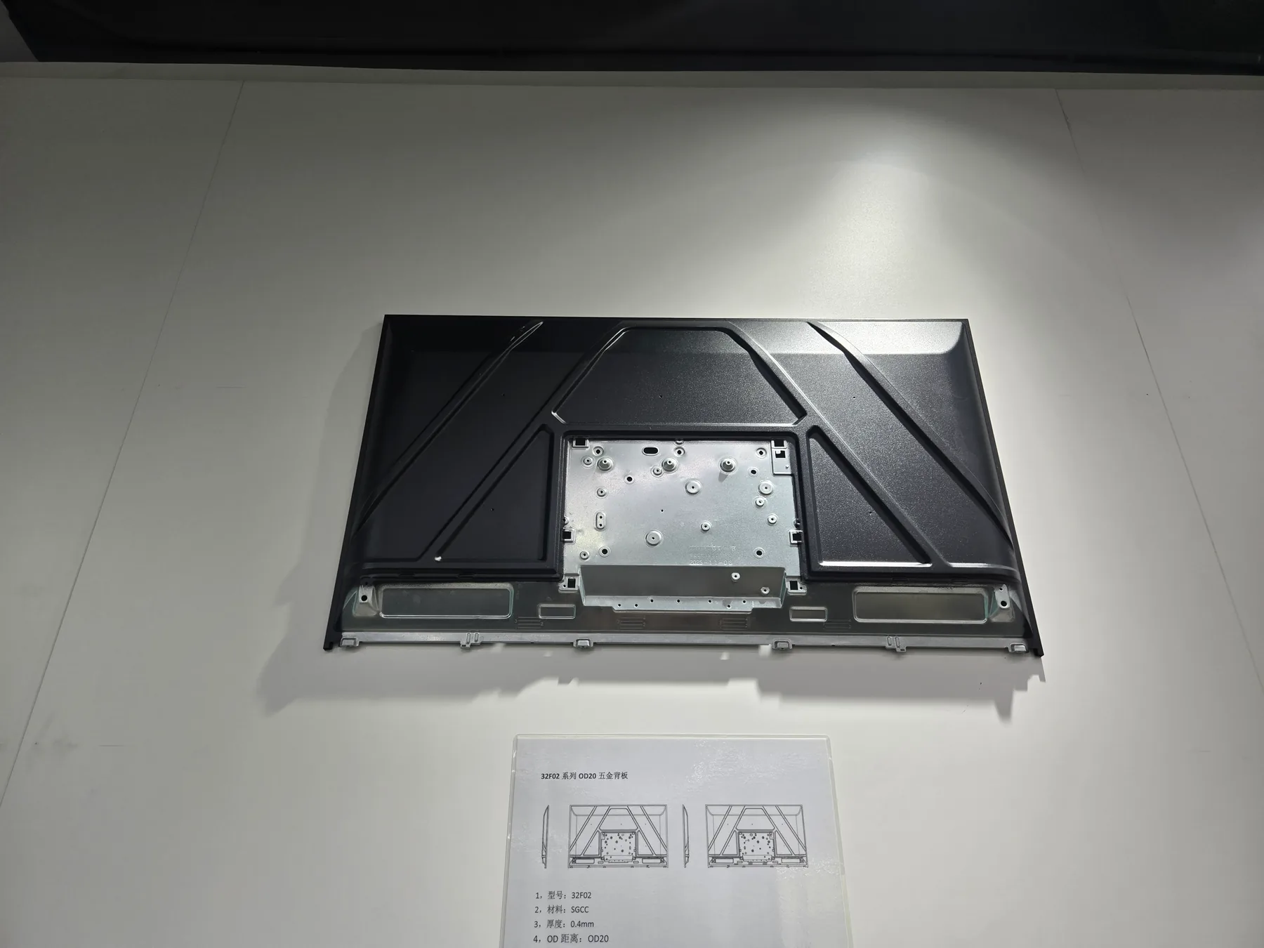
The cover shows a stamped panel in supplied company materials. It illustrates a production context and does not evidence a specific thickness, a structural analysis or a customer program. Every quantitative case in this article is labeled hypothetical. Elastic behavior, forming limits, flatness and assembly response must be confirmed for the actual geometry, material, tool and build.