
Article Snapshot
What this article covers
Stamping DFM asks how the geometry will behave through piercing, forming and release from the tools. Review feature interactions and functional regions before treating a minimum-distance guideline or a press-capacity figure as proof of feasibility.
- Distinguish clearance holes, locating features and openings before reviewing their manufacture.
- Review cut edges, bend transitions and stiffening features together.
- Define the regions and support conditions behind functional flatness.
- Compare process proposals using targeted evidence and explicit design decisions.
A TV metal back plate can contain a large number of apparently simple features: round holes, ventilation slots, connector openings, folded edges and shallow reinforcing forms. Difficulty often comes from their interaction. A hole that is easy to pierce in flat stock may move during a nearby forming operation. A bead intended to stiffen a panel may occupy the clearance needed by a circuit board. Stamping design for manufacturability, or DFM, makes those interactions visible before the tooling proposal becomes a fixed commitment.
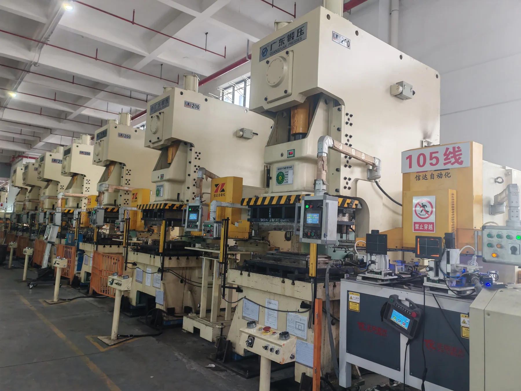
This review begins with an established part definition and asks what the proposed manufacturing route needs to preserve. It complements the drawing-review guide without repeating its file-control workflow. The cover is the supplied KINGSUN stamping-line photograph, press-line-105-detail.webp. It shows stamping presses; it does not identify the tool, part model, operation sequence or measured output for a particular TV program.
1. Define which features carry the assembly requirements
Mark each relevant region by purpose before discussing manufacturability. A clearance hole allows passage; a locating feature establishes position; a fastening region supports an attachment; a connector opening provides an access envelope. Similar-looking holes may therefore need different attention. Ask the product engineer which relationships determine assembly success and which dimensions can accommodate a manufacturing proposal.
Prepare a feature map that connects these purposes to the actual board, housing or bracket. Include areas where contact is prohibited, surfaces that must seat together and regions available for tooling contact. This gives the tool designer room to propose a practical route without treating the whole panel as equally critical. It also prevents a cosmetic or convenience dimension from accidentally receiving the same priority as a mounting interface.
The review output should distinguish fixed product requirements from negotiable geometry. For each proposed change, state what function must survive. “Increase space around this slot while preserving the cable insertion envelope” gives a useful engineering objective; “make stamping easier” leaves the product consequence undefined.
2. Review pierced holes and slots as manufactured features
Piercing uses a punch and die rather than producing an ideal cylindrical CAD wall. Xometry's stamping design guidance describes the burnished and fractured portions of a pierced edge and the risk of distortion when holes approach edges or bends. Its dimensional recommendations are supplier guidance for stated conditions, not universal TV back-plate limits.
For the actual part, ask the stamping engineer to review the smallest holes, narrow slots, remaining webs and clusters of nearby openings against material, thickness and proposed tool construction. Identify whether a critical hole is evaluated in the flat blank or after all forming. A convenient dimension on a flat development does not establish the final relationship between the hole and an assembled board.
Use the following discussion table to expose feature conflicts. The actions are review prompts, not preapproved design changes.
| Feature relationship | Question for the tool review | Product requirement to preserve |
|---|---|---|
| Mounting hole near a flange | Will forming alter the final hole shape or position? | Fastener engagement and board location |
| Narrow web between openings | Can the web remain stable through cutting and handling? | Required opening envelopes and structural continuity |
| Hole beside a reinforcing bead | Which operation creates each feature and what material moves? | Seating area and surrounding clearance |
| Dense ventilation pattern | How are the perforated region and adjacent forms supported? | Approved ventilation layout and assembly fit |
3. Make burr direction and edge condition explicit
A hole diameter alone cannot describe whether its edge is suitable beside a cable, insulating film or mating surface. Identify which side of each relevant feature faces that interface. Ask for the permissible burr direction and the agreed edge condition, including whether a secondary treatment is needed. Avoid using an undefined “burr free” note as a substitute for a measurable requirement.
Toolmaker Dayton Lamina explains punch-to-die clearance as a choice linked to material thickness, type and strength. Excessively tight clearance can create secondary shearing and increase stripping forces; excessive clearance can also produce an unsuitable edge. Its guidance shows why simply requesting the smallest clearance is not a reliable solution.
For purchasing discussions, specify the required result and let the tooling review establish how to achieve it. If burr removal is proposed, review its effect on the local interface and protective surface. Mark the affected zones so inspection can distinguish a critical cable-adjacent edge from an edge with a different permitted condition.
4. Review bends, flanges and transitions together
A flange should be reviewed with its neighboring holes, corner junctions and adjacent forms. Ask where the bend begins, what radius the finished part requires and how the short end regions will be supported. At intersecting flanges, the engineer should assess whether the proposed transition or relief preserves the intended seating surface and avoids interference with the housing.
SSAB's bending explanation identifies material properties, thickness and tooling setup as influences on the result. Its recommendations are explicitly limited to its products. Those principles justify asking about the actual material and tool; they do not justify importing press-brake settings into a matched stamping die or applying a radius from another steel grade.
Describe flange function in the review: is it an assembly stop, a stiffened edge, a fastening surface or a cosmetic boundary? Then consider how a change in angle or end relief affects that function. Where bend orientation relative to sheet rolling direction matters, request an explicit engineering assessment. The proposed blank orientation and tooling route must remain compatible with any resulting requirement.
5. Add stiffening where the structure benefits from it
Beads and embosses introduce out-of-plane geometry into a sheet. Their useful placement depends on the loads, supports and clearances of the actual structure. Altair's topography-optimization tutorial illustrates how bead layout can affect stiffness and vibration behavior under defined analysis conditions. Its oil-pan example provides no TV back-plate design values.
For a TV structure, begin by marking areas available for reinforcing forms and areas that must remain clear for boards, connectors, fastening tools or mating surfaces. Ask which span or local region needs support. A uniform decorative pattern is not evidence that the important load path has improved, and a deeper bead is not automatically the best answer when the space behind the plate is limited.
Assess the formed feature's footprint, transitions and relationship to neighboring holes. Request a proposed cross-section and a clearance review rather than approving only its outline in plan view. If analysis is used, record its load cases and restraints. A stiffness comparison becomes meaningful when the baseline and proposed design use consistent assumptions that reflect the intended assembly.
6. Define functional flatness by region and condition
“Keep the plate flat” can refer to several different needs: local seating around a fastener, a broad mounting region, a housing contact edge or clearance across an unsupported span. Identify the region and explain the consequence of shape variation there. An overall panel requirement should not silently replace a local seating requirement, or the reverse.
Agree whether evaluation occurs with the part free or under a defined restraint. Name the support points, orientation and any prescribed assembly condition. A fixture that pulls a flexible panel into shape answers a different question from a free-state check. Neither result can be interpreted properly if the support condition is missing from the report.
WorldAutoSteel's springback guidance explains elastic recovery after tool unloading and distinguishes angular change, sidewall curl and twist. It also notes that cutting openings can alter a panel's shape after forming. This is automotive sheet-forming background, not evidence that a TV part uses advanced high-strength steel. For a back plate, it supports checking final shape after the relevant operations rather than inferring it from the shape held inside a die.
7. Ask how the process sequence protects critical features
Review a proposed operation sequence at the level needed to understand risk. Identify when the blank is cut, critical features are pierced, reinforcing forms are created and perimeter flanges are formed. Ask how the workpiece is located and supported between these steps. The purpose is to discover dependencies, not to prescribe a particular die architecture before the supplier has assessed the part.
A useful question is whether an operation performed later could invalidate an earlier feature check. If a hole is pierced before a neighboring form, ask how final location will be confirmed. If an opening is cut after forming, ask whether the final panel condition has been evaluated afterward. Where a secondary operation is proposed, include its locating method in the discussion.
Include movement between operations in this review. Ask which regions are available for gripping, which surfaces may contact supports and how orientation is maintained. A proposed handling contact should be assessed against the feature map rather than assumed harmless because it occurs outside the die. If a local seating region also serves as a handling support, identify that shared role before deciding what evidence is necessary.
KINGSUN's published metal stamping capability includes television metal structures and project-specific tooling support. The actual press assignment, operation sequence, feature limits and corrective steps still require review of the controlled geometry. A production-area photograph or maximum press-capacity figure cannot establish these decisions for an individual part.
8. Resolve a hypothetical hole, opening and bead conflict
Hypothetical engineering example: a proposed back plate places a board-mounting hole beside a connector opening. A new reinforcing bead passes between them. The board must retain its position, and the connector must remain accessible through the opening. No dimensions, customer identity or production result are implied by this scenario.
The review first marks the board seating area and the connector insertion envelope. The stamping engineer then identifies the proposed order for piercing and bead forming and explains which surrounding regions may be affected. The product engineer compares three options: move the bead, modify its termination, or revise the opening boundary where functional clearance permits. Moving the mounting hole remains a separate assembly decision.
The team records the chosen geometry as a candidate, then identifies the evidence needed: final mounting-hole relationship, local seating and connector access after forming. If the bead moves, its intended stiffening purpose must also be reconsidered. This approach prevents an isolated improvement in tool access from being accepted while its structural or assembly consequence remains unresolved.
9. Choose evidence that answers the actual DFM question
A generic dimensional report may miss the feature interaction that prompted a change. Match each question to evidence collected in the relevant final condition. The following planning matrix helps the design and manufacturing teams agree what would resolve uncertainty; it does not specify a universal sampling plan.
| DFM uncertainty | Useful evidence to request | Decision supported |
|---|---|---|
| Pierced edge beside wiring | Agreed edge assessment on the identified side and region | Accept the condition or define additional treatment |
| Hole affected by forming | Final feature measurement with its locating references recorded | Accept sequence or reassess geometry and tooling |
| Local board seating | Regional shape check under the defined support condition | Confirm seating or investigate the local form |
| Reinforcement conflicts with clearance | Section review and applicable assembly-clearance evaluation | Retain, reposition or redesign the feature |
Record part identity, material condition and the operations completed before evaluation. A hand-adjusted sample or an intermediate part can be informative, but its condition must be visible to the reviewer. When evidence changes the proposed route, revisit the associated feature checks instead of treating the earlier result as automatically transferable.
Agree the meaning of an unsuccessful result before the check begins. A clearance failure might require a geometry decision, while an unexplained regional shape difference might require investigation of the support setup first. Recording the question alongside the result helps avoid changing the tool in response to an ambiguous measurement.
10. Close DFM with specific decisions and remaining limits
Close each issue with the retained requirement, proposed geometry or process action, responsible reviewer and evidence needed for disposition. Distinguish an accepted design change from a supplier suggestion still awaiting evaluation. The resulting record should explain why the candidate is suitable for the next activity and which questions remain open.
For a productive KINGSUN discussion, share the finished-part geometry, specified material and thickness, critical feature map, relevant mating-part envelopes and intended volumes. Identify negotiable areas directly. This lets the review concentrate on manufacturing interactions while the customer retains authority over product function. Tooling feasibility, production acceptance and assembly validation each require their own applicable evidence.
Good stamping DFM preserves the relationships that matter through the proposed manufacturing route. Its value is a smaller set of explicit, testable decisions about holes, edges, forms and panel shape. It should leave the next engineer able to identify both the agreed direction and the precise limit of that agreement.
11. Sources and engineering boundaries
These primary technical resources support the manufacturing principles discussed above. Supplier-specific ratios, software examples and automotive material behavior are not KINGSUN specifications. The tables and hypothetical scenario are original planning aids; this article establishes no numerical tolerance, certified performance or customer production result.