
Article Snapshot
What this article covers
Two parties can measure the same back plate and reach opposite conclusions without either being careless. This guide defines the measurement state, datum, fixture, point plan and acceptance logic so flatness becomes a shared, repeatable decision.
- State whether the part is measured free or restrained.
- Choose datums that match the assembly, not convenience.
- Control gravity, support and handling during the check.
- Separate forming distortion from assembly-induced distortion.
A flatness disagreement is rarely about the measuring instrument. One team places the back plate on a surface table, measures the gap at a corner and reports a part that is out of specification. Another team installs the same part in a housing, torques the screws and finds the gap has closed. Both measurements can be correct and they answer different questions. Until the state is agreed, the number has no shared meaning.
This guide is about that agreement. It covers free and restrained states, functional datums, fixture design, gravity and handling effects, point planning and the boundary between forming distortion and assembly distortion. It is written for structural parts on a television program where flatness affects appearance, fit, sealing, connector alignment or the feel of the final product. All numbers here are illustrative; no universal flatness value is proposed.
1. Separate the shape question from the measurement state
Flatness is a property of a surface relative to a reference. The measurement state is everything else: how the part is supported, where gravity acts, what is clamped, what is free to spring back and which reference frame the instrument uses. Change any of those and the reported value can move, even when the physical part has not changed.
A stamped panel is an elastic body with residual stress from forming. It will deflect under its own weight if it spans an unsupported area, and it will distort when fasteners pull it against a housing that is not perfectly flat. A thin panel placed face-down on a table is conforming to the table as much as being measured; a panel held only at three points is revealing its own shape. Neither example is wrong, but they cannot be compared.
The practical consequence is that a drawing note such as "flatness 1 mm" is incomplete. It needs a state, a datum scheme, a support condition and a point distribution. Without those, a supplier and a customer can pass the same shipment through their own checks and disagree about the result with complete technical sincerity.
2. Define free and restrained states explicitly
The free state describes the part supported so that it can take its natural shape, with gravity either minimized or applied in a defined direction. The restrained state describes the part fastened or clamped as it will be in the assembly. Both are useful, and they answer different questions: the free state tells you what the forming process produced, and the restrained state tells you what the product will experience.
ISO 10579 addresses the verification of non-rigid workpieces and the need to state the restraining conditions when a part cannot be measured in a free state. That is the formal version of a simple manufacturing truth: for a flexible part, the fixture is part of the specification. Television back plates are not aerospace structures, but the logic applies because a large thin panel deflects under its own weight.
State the choice in words on the drawing or in the inspection plan. "Measured in free state, supported at the three datum targets shown" and "measured after assembly to the housing with fasteners at the specified torque" are both usable. A note that simply says "flat within 0.8 mm" is not, because the reader must guess which of those two conditions was intended.
3. Choose the datum that matches the assembly
A datum is a reference established from real features on the part, and it should reflect how the part is located in the product. If the back plate seats on a housing ledge and is located by two pins, those are the natural primary and secondary references. Choosing a convenient edge or a random area of the surface instead creates a measurement that is easy to perform and hard to correlate with fit.
ISO 5459 provides the vocabulary and rules for datums and datum systems; ISO 1101 provides the geometric language used to express the requirement. The engineering decision is which features truly control location. On a stamped back plate the candidates are usually a formed seating surface, two locating features and a mounting plane. Inspect those first, then judge the rest of the surface relative to them.
Be careful with a datum taken from the very surface being evaluated. Using the whole back face as its own reference hides the shape you are trying to measure, because the reference floats with the defect. A better arrangement fixes a small number of targets that represent the real contact and evaluates the remaining surface against that frame. This is also the arrangement a fixture can reproduce.
4. Design the fixture before the measurement
If the state is defined, the fixture follows. A free-state check needs supports at defined targets and a way to avoid clamping the part flat. A restrained-state check needs the same contact pattern as the assembly, with fasteners applied in the same sequence and to the same torque. A fixture that imitates neither produces a number that belongs to the fixture.
Support location matters more than support stiffness for a flexible panel. Three points define a plane and let the part settle; four points can rock unless the supports are adjustable or the part is allowed to conform. Clamps should be placed where the assembly places fasteners, not wherever it is convenient to hold the part down. If the assembly uses clips rather than screws, model the clip force rather than substituting a clamp.
Record the fixture with the same discipline as the gauge. Give it an identifier, a revision, a support map and a verification interval. When a fixture drifts, every measurement made on it is suspect, and the resulting argument is much harder to resolve than a simple gauge calibration issue. A drawing that depends on a restrained state is implicitly depending on that fixture, so its control belongs in the quality plan.
5. Control gravity, support and handling
A large panel sags between supports under its own weight, and the amount depends on orientation. Measuring a back plate standing on edge is not the same as measuring it lying face-up. The difference is usually small for a stiff part and can be significant for a thin, large one, which is exactly the case where flatness matters most.
Standardize the orientation and the time allowed for the part to settle. A part taken directly from a stack may still be warm or elastically deformed by the stack; a part lifted by one corner will bend before it is placed. Let it rest on the supports, in the specified orientation, for an agreed interval before reading. This is a procedural detail that removes a whole class of unexplainable variation.
Handling also affects the part after measurement. A panel that is measured flat and then carried by two corners can be permanently set if the material yields. State how the part is lifted, how it is stacked and how many parts can be stacked before the bottom one is at risk. Packaging design and flatness are connected, and the connection is worth stating explicitly rather than discovering at the customer's receiving dock.
6. Measure the regions that actually function
A single flatness value across an entire panel averages regions with completely different jobs. The central mounting field has to be flat enough for the board and bracket. The perimeter flange has to seat against the housing. The area around the connector cutouts has to keep the ports aligned. The lower opening region may need to stay clear of a stand or a cable route.
Build a region map and give each region a function and an acceptance approach. A flatness requirement over a small functional area is often more useful than a loose requirement over the whole surface, because it points the process at the area that matters. It also prevents a supplier from achieving a good global number by distorting a region that nobody measured.
Planning table, not an acceptance specification: the example below shows how the decisions connect. The acceptance column is a placeholder to be replaced by the program's own requirement.
| Region | Functional role | State | Datum and support | Points | Acceptance to define |
|---|---|---|---|---|---|
| Central mounting field | Board and bracket seating | Restrained | Housing contacts, fastener pattern | Grid across the seating area | Gap and local form at fastener points |
| Perimeter flange | Housing seat and edge stiffness | Free and restrained | Seating surface, two locators | Along the flange, both sides | Contact continuity and twist |
| Port region | Connector alignment | Restrained | Board datum and housing contact | Around each cutout | Position relative to the port axis |
| Lower opening area | Stand clearance and cable route | Free | Three-point support | Edge and span | Shape that preserves clearance |
7. Distinguish springback from assembly-induced distortion
When a panel is not flat, the cause can be in the forming process or in the assembly. Springback happens when the tool releases and the elastically stored energy redistributes; it is a property of the formed part. Assembly distortion happens when the part is forced to match a housing, a bracket or a fastener pattern that does not match its natural shape.
The two are separable. Measure the part free, then measure it restrained on the same datum, and compare the two maps. A part that is flat free and distorted when fastened is being forced by the assembly. A part that is already distorted free is carrying a forming problem into the assembly. A part that is distorted in both states has both issues, and fixing only one will not close the complaint.
Assembly-induced distortion is not automatically a part defect. If the housing surface is not flat, or the fastener pattern pulls the panel into a twist, the fix may belong to the housing, the assembly sequence or the torque plan rather than the stamping. This is why the measurement plan should include the mating part: without it, the supplier is being asked to compensate for a condition outside the supplied drawing.
8. Set acceptance by function, not by one global number
The acceptance rule should follow from what the region must do. A seating flange needs contact; a cosmetic face needs an appearance free of visible waves under the specified lighting; a port region needs alignment within the connector's allowance; a mounting field needs to avoid preload that cracks a boss or relaxes a fastener. These are different criteria and they can coexist in one inspection plan.
Where a number is used, define the reference, the state, the zone and the evaluation method. A peak-to-valley value over a defined area, taken from a defined datum in a defined state, is repeatable. A single maximum deviation quoted without those conditions is not. Where the requirement is functional contact, a feeler or contact check may be more meaningful than a form tolerance, provided the check itself is defined.
Acceptance also needs a decision rule for edge cases. If the part is within the global requirement but fails a functional region, the functional region governs. If it exceeds a global guide but all functional regions pass, the program should have anticipated that case in the requirement rather than negotiating it after delivery. Writing the priority order into the inspection plan avoids that argument later.
9. Work through a hypothetical corner-lift dispute
Hypothetical planning example, not a KINGSUN customer case: a supplier reports 1.2 mm of corner lift in the free state and ships the lot. The customer measures the assembled unit, sees 0.4 mm at the same corner and rejects the shipment as inconsistent with the agreed number. Neither measurement is wrong; the two teams are measuring different states.
The review starts by writing down both procedures. The supplier supports the panel on a surface table, face-down, with no clamps. The customer measures after assembly, with the housing fastened and the stand installed. The free-state number reflects the forming result; the assembled number reflects the housing pulling the corner into contact. The disagreement is about which condition the purchase requirement intended.
The teams agree on a two-state plan: free state at the supplier for process control, restrained state at the customer for fit acceptance, with a shared fixture definition and a common point map. The first lot is measured under both conditions and the results are compared. The corner lift turns out to be a real forming trend, visible in the free state, that the assembly happens to mask. The lesson is that the assembly can hide a process drift, so production monitoring cannot rely only on the assembled check.
10. Write the requirement so receiving can repeat it
A repeatable requirement fits on one page and leaves nothing essential to memory. It names the state, the datum features, the support locations, the orientation, the settling time, the regions, the point pattern, the instrument class and the acceptance rule. It also names the fixture and its revision, because a restrained check without a controlled fixture is not reproducible.
Ask receiving to run the plan on the first delivery and compare notes with the supplier's report rather than only comparing pass or fail. A comparison of point maps explains a difference in minutes; a comparison of single numbers can consume weeks. Where measurement systems differ, a correlation study on a few parts is a better investment than a debate about whose gauge is right.
The structural component inspection guide covers the broader inspection and release sequence, and the drawing review guide covers how datums and revisions reach the supplier. For a new program, share the assembly condition, the fixture concept, the functional regions and any historical complaint with the project team so flatness can be defined before the first tool is cut. KINGSUN's stamping process overview describes where forming and flatness control sit in production.
11. Sources and engineering boundaries
These references support the vocabulary and the general rules for measuring flexible parts. They do not provide a television flatness value, and none of them replaces the program's own drawing and inspection plan.
- ISO 10579:2010 — Geometrical product specifications: non-rigid parts: restraining conditions during verification. A related revision project is in development; no clause text is reproduced here.
- ISO 12781-1:2011 — Flatness, vocabulary and parameters and ISO 12781-2:2011 — specification operators.
- ISO 5459:2024 — Datums and datum systems.
- ASME Y14.5-2018 — Dimensioning and tolerancing: background on the alternative geometric language; not mixed with ISO symbols here.
- NPL Good Practice Guide 41 — CMM measurement strategies: the trade between point count, confidence and cost.
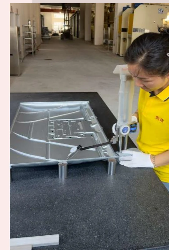
The cover shows a workshop dimensional check in supplied company materials. It does not evidence a specific tolerance, fixture or acceptance decision, and the corner-lift case is hypothetical. Flatness requirements, datum schemes and fixture designs must be confirmed against the actual part, the mating assembly and the agreed inspection method.