
Article Snapshot
What this article covers
Warpage is not the same as shrinkage, and a molded housing can be dimensionally correct yet still fail to fit. This guide links wall sections, cooling, packing and orientation to a measurement and fit plan that separates design causes from process causes.
- Distinguish uniform shrinkage from differential shrinkage.
- Read wall and rib sections as a cooling problem.
- Measure the free and assembled states separately.
- Predict fit with a stack instead of one warpage number.
A rear housing comes out of the tool visibly bowed, and the first question is always whether the part is wrong or the process is wrong. The answer is usually that both contribute, in proportions that cannot be guessed from the shape alone. A housing can also look flat and still fail to fit, because the distortion appears only after the screws pull it against the chassis or after the part cools fully.
This guide covers warpage in injection-molded television rear housings: what it is relative to shrinkage, how wall and rib sections drive it, how gate position, packing and orientation contribute, how to measure it in a state that means something, and how to separate a design fix from a process fix. It is a diagnostic framework, not a set of molding parameters. Every number below is illustrative, and the actual window must be established on the tool and the material.
1. Separate shrinkage from warpage
Shrinkage is the reduction in size as the polymer cools and solidifies. Every molded feature shrinks, and a well-designed part accounts for it with a mold dimension that is larger than the final part. Warpage is a different phenomenon: it is the loss of intended shape caused by uneven shrinkage through the part or across its area. A part can shrink uniformly and stay flat, or shrink by the right average amount and still twist.
This distinction matters because the fixes are different. A uniform dimensional offset is corrected in the tool steel. A warp is corrected by changing the balance of cooling, packing, wall section or fiber orientation. If a team treats a warp as a shrinkage error, it will keep adjusting dimensions while the shape continues to move.
ISO 294-4 describes the determination of molding shrinkage, and its free-shrinkage concept is a useful reference point: the shrinkage measured on an unrestricted test specimen is an upper bound, not a prediction of a constrained production part. ISO 20457 addresses tolerances and acceptance for plastic molded parts and reflects the fact that plastic parts need their own tolerance logic rather than a translated metal specification.
2. Read the wall and rib section as a cooling problem
Thick sections cool more slowly than thin ones, and they shrink more as they do. A housing with a thick boss, a thin nominal wall and a rib that is nearly as thick as the wall will have three different cooling histories in one local area. The result is differential shrinkage, and where the geometry restrains it, the part distorts or develops sink marks or internal stress.
Look at the section, not just the nominal wall callout. A rib that is too thick at its base acts as a local mass and pulls the surrounding surface as it cools. A boss with a heavy wall does the same. Conventional design practice reduces rib thickness relative to the nominal wall and adds a radius at the base, but the right proportion depends on the material and the geometry. The point is to make the section visible in the review rather than trusting the wall thickness note.
Wall transitions deserve the same attention. A sudden change from a thin cosmetic wall to a thick mounting pad creates a cooling gradient and a likely warp or sink. A gradual transition distributes the effect. Where a thick section is unavoidable, a core-out or a redesign of the attachment can reduce the mass without losing function.
3. Follow the flow: gate, packing and orientation
The gate determines how material enters the cavity, and therefore how it fills, how it packs and how molecules or fibers orient. A single gate at one end of a large housing creates a long flow path with pressure loss along the way; the far end may be packed less than the near end. That difference becomes a shrinkage difference and a warp.
Packing pressure and time matter as much as the gate position. If the gate freezes before the thick section has been packed, that section shrinks more than the rest. If packing is excessive, the area near the gate is over-packed and stressed. Neither condition is visible on the part until it warps or until it is measured after cooling.
For filled materials, orientation adds another layer: shrinkage along the flow direction differs from shrinkage across it. A housing with a long flow path and a changing direction can warp even when the wall is uniform. Material supplier guides from Covestro and SABIC describe non-uniform cooling and wall-thickness variation as sources of differential shrinkage and warpage, and Moldflow's documentation lists differential cooling, differential shrinkage and orientation as contributors. These are mechanism descriptions from material and software suppliers, not process settings for a specific part.
4. Control mold temperature symmetry
If one side of the mold runs hotter than the other, one side of the part cools later and shrinks differently. The result is a bow toward the hot side or a twist that follows the temperature gradient. Mold temperature symmetry is therefore a direct warpage control, not a comfort setting.
Verify the actual mold surface temperature at several points, not just the setpoint on the controller. Cooling channel layout, flow rate, scale and the thermal condition of the surrounding steel all affect what the plastic sees. A channel that is partially blocked or a circuit that is plumbed in the wrong order can produce a persistent asymmetry that no amount of packing adjustment will fix.
Cooling time is the other half. Shortening it to raise output leaves the part hotter when it is ejected, and a hot part is softer and more likely to deform under ejection or handling. The correct time is the one that lets the part reach a stable enough state, which is a function of the thickest section, not the average wall. A trial that shortens cooling without checking the resulting shape is trading a measurable gain for an invisible risk.
5. Measure in the state that matters
A warpage number without a measurement state is as ambiguous for a molded part as for a stamped one. The free state after 24 hours of conditioning, the state immediately after ejection and the state after assembly are three different conditions. The assembly cares about the restrained state; the molding process cares about the free state.
Define the conditioning time and temperature, the support points and the orientation. A large housing resting on a table will conform to the table; a housing supported at three points will show its own shape. Record the datum features used for the measurement, and keep them the same across trials so the results are comparable.
Measure both the global shape and the local interfaces. A housing can have an acceptable overall bow and still fail at a specific screw boss or a connector opening. A point map over the seating surface, the boss heights and the port region is more useful than a single maximum deviation, because it shows where the fit problem will appear.
6. Predict fit with a stack, not a single warpage number
Fit is the result of several contributors: the housing shape, the chassis shape, the boss heights, the screw positions, the fastener clearance and the assembly sequence. A warpage value is one input to that stack. Using it as a pass-or-fail criterion on its own can reject a part that assembles well and accept one that does not.
Build the stack around the interfaces that matter. If the housing seats on a chassis ledge, the gap along that ledge is the relevant output. If it is held by screws at eight points, the local pull at each screw and the resulting stress are relevant. If it carries a stand or a wall bracket, the distortion under load matters more than the free shape.
Include the assembly sequence. Tightening screws from one end to the other pulls the part progressively and can produce a different final shape than tightening from the center outward. A torque plan is part of the fit design, and it belongs in the same discussion as the part tolerance.
7. Separate design fixes from process fixes
When a housing warps, the team usually has two families of options. Design fixes change the part: wall thickness, rib proportions, boss geometry, gate location, cooling layout, ejection strategy. Process fixes change the running condition: melt temperature, mold temperature, packing pressure and time, cooling time, ejection speed. Both families can reduce warpage, and they have very different costs.
A process fix is usually faster to try but may be narrow. It can bring a part into tolerance for one material lot and one machine, then drift when conditions change. A design fix is slower and may require tool work, but it addresses the mechanism and is more robust across the production window. The right choice depends on whether the warp is a marginal condition or a structural consequence of the geometry.
Planning table, not a diagnosis: the observations below are starting points for investigation. Each one has more than one possible cause, and the evidence must decide.
| Observation | Likely mechanism | Evidence to collect | Design lever | Process lever |
|---|---|---|---|---|
| Overall bow along the long axis | Asymmetric cooling or packing | Mold surface temperatures, part map | Cooling layout, wall balance | Temperature, packing |
| Corner lift | Differential shrinkage toward the edge | Corner heights, gate distance | Rib and edge section | Packing profile, cooling time |
| Sink over a rib or boss | Local mass cooling late | Section cut, surface map | Rib or boss thickness | Packing, cycle |
| Spring-back after assembly | Stored stress and forced fit | Free vs restrained map | Interface and boss position | Stress reduction, annealing |
8. Validate with a pilot that represents production
A single trial shot proves that a condition can be reached; it does not prove that the condition holds. A pilot run should use the production tool, the production material and a representative machine, and it should run long enough to show that the process is stable rather than just capable. Measure parts from the start, middle and end of the run.
Include the assembly in the pilot. A housing that measures well free and distorts when fastened has not been validated. Assemble a sample with the production chassis and the production torque plan, then measure again. If the assembled result is acceptable but the free state is marginal, the program should know that the margin is being provided by the assembly, because that margin can disappear with a different chassis or a different operator.
Define what changes are allowed during the pilot and record them. A process adjustment made mid-run without a record turns the results into a mixture of conditions. If the pilot needs a change to reach acceptance, that is a finding, not a detail to smooth over.
9. Work through a hypothetical bow in a rear housing
Hypothetical planning example, not a KINGSUN customer case: a large rear housing shows about 2 mm of diagonal corner lift in the free state. When it is clamped to the chassis the lift closes, but the screw bosses at two corners show whitening at the base, which suggests the material is being strained to close the gap.
The team first standardizes the measurement: 24 hours of conditioning, three-point support, a recorded datum and a point map. The map shows the lift is concentrated at two opposite corners and that the bosses at those corners are also the tallest. A section review finds those bosses have a heavy wall compared with the nominal skin, and the cooling circuit on that side of the tool runs slightly warmer.
The process trial reduces the temperature asymmetry and extends cooling, which brings the free-state lift down. The design review then reduces the boss wall and adjusts the corner rib, which removes the remaining stored stress. The final validation uses the production chassis, and the assembled part shows no whitening at the bosses. The lesson is that the warp had both a process and a geometry contribution, and the assembled symptom pointed to the second one.
10. Write the requirement into the drawing and the RFQ
The drawing should define the surfaces and features that control fit, the acceptable shape in the relevant state, and the datum scheme used to check it. It should not rely on a single general tolerance for a part whose function depends on specific interfaces. Where a boss height or a seating surface is critical, dimension it directly.
In the RFQ, provide the 3D model, the wall and rib sections, the gate and cooling concept if it is fixed, the material grade, the current process window, the measurement state, the assembly conditions and any observed complaint. Ask the supplier to describe how warpage will be controlled and how the first article will demonstrate it. A response that only promises "good flatness" is not reviewable.
The injection-molding DFM guide covers the design features that prevent these problems, the metal versus molded comparison covers the route decision, and the injection molding process overview describes the production context. A specific warpage question can be raised through the project contact with the model, the measurement state and the assembly condition.
11. Sources and engineering boundaries
These references describe shrinkage, tolerances and warpage mechanisms. They do not provide a warpage limit, a mold temperature or a packing profile for a specific housing.
- ISO 294-4:2018 — Determination of molding shrinkage: free shrinkage is an upper bound rather than a part dimension.
- ISO 20457:2026 — Tolerances and acceptance conditions for plastic molded parts: plastic parts need their own tolerance logic.
- Covestro — injection molding guidance: non-uniform cooling and wall variation as sources of differential shrinkage.
- SABIC — injection molding guide: wall variation, over-packing and differential cooling as warpage contributors.
- Autodesk Moldflow — contributors to warpage: differential cooling, differential shrinkage and orientation.
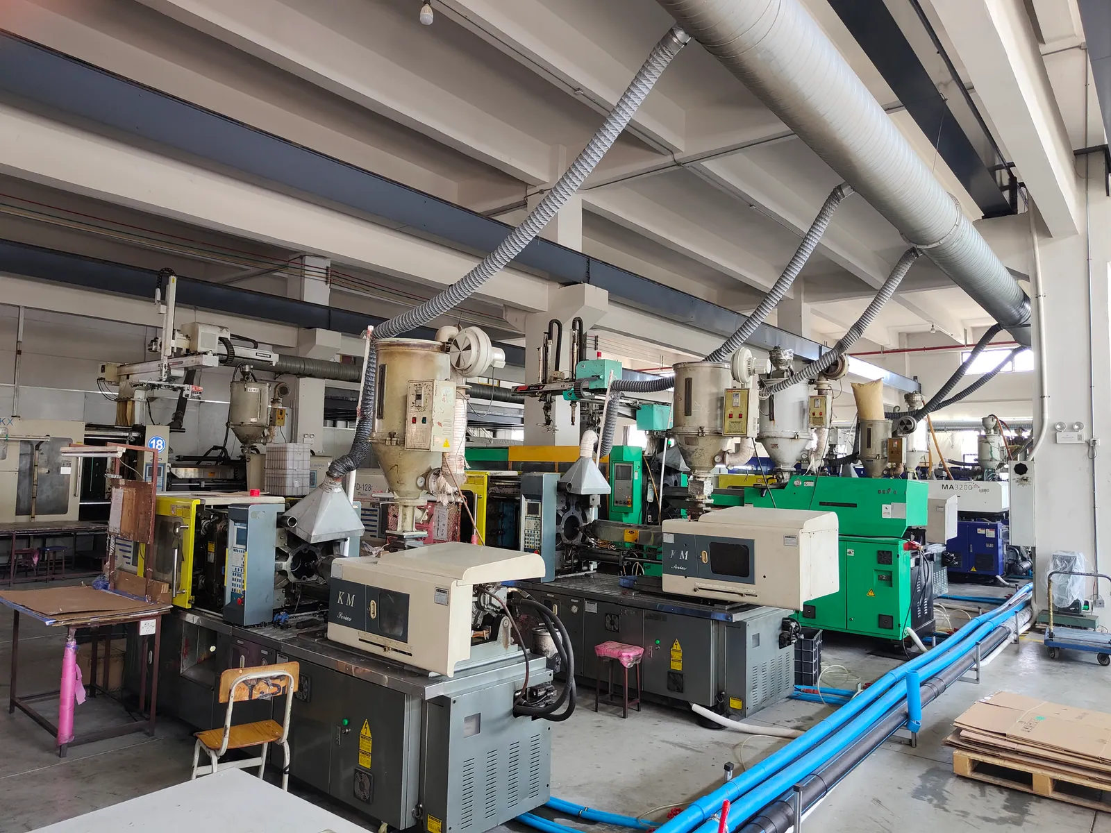
The cover shows injection molding equipment in supplied company materials. It does not evidence a warpage value, a process window or a customer program, and the corner-lift case is hypothetical. Warpage control must be established on the actual tool, material and assembly.