
Article Snapshot
What this article covers
A connector cutout that fits on the bench can still fail in the product. This guide builds the opening from the plug envelope, the board datum chain and a tolerance stack, then carries it through burr direction, coating and assembly sequence.
- Define the cutout from the plug, cable and hand envelope.
- Build a datum chain from the board to the back plate.
- Use a tolerance stack instead of a nominal outline.
- Control burr, masking and assembly sequence together.
The complaint is familiar: the cable goes in on the sample table but not on the assembled unit, or it seats only when the panel is pushed inward. The connector itself is fine. The opening was drawn from a nominal outline, the board sits a little off its nominal position, the panel has some springback, the coating has some thickness, and the sum of those small offsets is larger than the clearance that was left.
This guide covers the interface between a board-mounted connector and a stamped or molded back plate. It builds the cutout from the mating envelope rather than the connector body, establishes a datum chain from the board to the plate, shows how a simple tolerance stack changes the required clearance, and covers burr direction, coating and assembly sequence. The numbers used are illustrative. Connector dimensions must always come from the approved component specification.
1. Start from the connector, not the hole
A cutout exists to let something through. The something is not only the connector body: it is the plug shell, the overmold, the cable bend, the hand that pushes the plug home and sometimes a screwdriver or a test probe. Drawing the opening as the connector outline plus a uniform gap ignores most of that list.
Begin with the approved connector drawing and its mating plug. Identify the interface plane, the insertion depth, the latch or retention feature and the direction from which the plug must approach. Then add the cable: a cable leaving a recessed port needs bend space, and a straight plug with a molded strain relief can need more room than the connector body suggests. Finally, add the hand and tool clearance needed to insert and remove the plug in the real product position.
This envelope is a design input, not a supplier assumption. If the brand owner has a preferred cable or a specific plug, its dimensions belong in the interface package. If the port must accept a range of third-party cables, the envelope should represent the largest credible plug and the worst credible bend, not the smallest sample on the engineer's desk.
2. Build the interface envelope: plug, cable, hand and tool
Build the envelope in layers. The first layer is the connector-to-plug fit: the shell, the contact block and the retention geometry. The second is the cable path: the minimum bend radius the cable can tolerate, the direction it must leave, and whether a right-angle or straight plug is expected. The third is human access: finger clearance around the plug body, space for a grip, and the approach angle a person can actually achieve with the television in its installed position.
Each layer should be dimensioned against a clear reference. A recess depth measured from the outer surface, a lateral clearance measured from the connector centerline and a vertical clearance measured from the board surface are all usable. A vague note like "allow enough space for the cable" is not, because it cannot be checked and it will be interpreted differently by each supplier.
Where the port sits in a recess or a pocket, the envelope becomes three-dimensional and the panel thickness matters. A thick panel with a straight cut gives a deep tunnel that limits the plug's approach angle. A chamfer, a formed flare or a locally thinned area can restore access, but each changes the tool and the edge condition. Review the approach angle with the actual plug, not with a cylinder that represents only the connector body.
3. Establish the datum chain from board to plate
The cutout must align with the connector, and the connector is positioned by the board, which is positioned by its own standoffs and screws. The chain therefore runs from the board datum, through the board mounting features, through the back plate mounting features, to the cutout. Each link has its own tolerance, and the cutout inherits all of them.
Write the chain down explicitly. Which board feature locates the connector in the plane? Which standoffs set the board height? Which plate features locate the board? Which features locate the plate in the housing? A chain with an unstated link is where the surprise comes from, because everyone assumes it is exact.
ISO 5459 provides the datum vocabulary and ISO 1101 the geometric language, while the program's own drawing decides which system applies. The engineering work is to make the chain reflect the assembly. If the board is located by two holes and a surface, those are the references. If the board floats on standoffs with clearance, that clearance is a contributor, not a detail to be ignored until the pilot build.
4. Calculate the cutout from tolerances, not from nominal
A nominal stack adds the nominal positions and checks the nominal plug. A tolerance stack adds the permissible variation in each contributor and asks whether the worst credible combination still allows insertion. For a connector interface, the relevant contributors usually include board position, board thickness, standoff height, plate position, plate thickness, cutout position, cutout size, coating thickness and plug geometry.
A simple worst-case addition is enough for many programs and is easy to explain. Add the positive deviations in one direction and the negative deviations in the other, then check the remaining clearance. If the result is negative, the interface interferes in the worst case even though every part is individually within its own tolerance. That is not a manufacturing defect; it is a design stack that was never closed.
A statistical approach can show that the worst case is unlikely, but it requires assumptions about distributions and process control that a new program may not have. For a first article, the conservative addition is easier to defend and easier to verify. Either way, record the contributors, the values and the source of each value so the stack can be reviewed when a component changes.
Planning table, not an interface specification: the fields below are the ones that most often go unrecorded. Each needs an owner and a value before the opening can be closed.
| Interface field | What to define | Source of truth | Tolerance contributor | Verification |
|---|---|---|---|---|
| Connector and plug | Part number, insertion depth, latch | Approved component specification | Connector position on the board | Insertion check with the production plug |
| Cable envelope | Bend radius and exit direction | Approved cable data or customer sample | Cable build variation | Fitted assembly with the real cable |
| Board position | Datum, standoff height, thickness | Board drawing and assembly model | Board and standoff tolerances | Measured at the port region |
| Plate position | Locating features and bend angle | Plate drawing and fixture plan | Forming and assembly variation | First-article dimension check |
| Opening | Size, position, end radius, flare | Interface drawing | Punch and die wear | Measured at the defined datum |
| Edge and coating | Burr side, deburr, mask zone | Drawing note and finishing plan | Coating thickness and mask position | Visual and gauge check |
5. Decide burr direction and edge treatment
A cut edge has a burr on one side, and the side is set by the tool. On a connector cutout the burr can matter more than elsewhere because the plug, the cable jacket and the customer's hand all come close to the edge. A burr facing outward is a handling and appearance risk; a burr facing inward can abrade a cable or interfere with the connector shell.
State the burr direction in product terms. "Burr toward the inside of the enclosure" is unambiguous; "burr down" depends on how the part is oriented in the press. Also state the acceptable edge condition: a defined deburr, a rolled edge, a formed flare or a coating-covered edge. Each option has a different cost and a different effect on the insertion envelope.
For a molded rear housing the equivalent decision is the tool's steel direction and the parting line position. A parting line that crosses a port opening can leave a step in the insertion path. The design review should place the parting line away from the functional edge or specify the finishing operation that removes the step.
6. Plan the assembly sequence and service access
A cutout that is generous enough on paper can still be unreachable in the build sequence. If the board is installed after the back plate, the connector must pass through the opening during assembly. If the board is installed first, the plate must be lowered over the connectors without trapping a cable. The order changes which clearance matters.
Walk through the assembly in the actual order, with the actual fixtures. Note where a cable is routed before the plate closes and whether it can be pushed aside. Note whether the port opening is used as an access point for a screwdriver or a test probe, and whether that access is temporary or permanent. A temporary access need does not justify a permanent oversized opening, but it may justify a service feature.
Service access deserves the same treatment. If a technician must disconnect a cable with the television mounted, the approach angle and the finger clearance are part of the design. If the port is only accessed with the unit off the wall, the requirement is easier. Clarify which case the product supports, and design to that case rather than to both.
7. Check tooling direction and panel distortion around the opening
An opening near a bend or a bead is affected by the forming sequence. If the cutout is pierced before a nearby bead is formed, the material around the opening may stretch and the edge may distort. If it is pierced after forming, the punch must work on a curved surface and the die must support the area. Both routes are possible; neither is free.
Ask the tooling engineer to review the cutout in the context of the strip layout and the station sequence. A cutout close to the panel edge may need more material in the blank, and a cutout close to a stiffening feature may need a relief. The goal is to keep the opening geometry stable through forming, because a distorted opening changes the insertion envelope that the stack was built around.
Distortion around the opening also affects appearance. A large cutout in a thin panel can create a visible pull or a wave on the outer face, especially if the surrounding area is cosmetic. A small bead or a local emboss around the cutout can stiffen the perimeter, but it must not intrude on the plug envelope. The tooling and structural reviews have to happen together.
8. Coordinate with coating, masking and labelling
Coating thickness is a real contributor to the interface. A painted or powder-coated edge reduces the opening, and masking that stops short of the edge can leave a step. If the port must present a clean, conductive or specified surface, the coating and masking plan belongs in the interface drawing, not in a separate finishing note.
Masking also affects appearance. A mask line around a connector opening is visible, and its position relative to the edge must be consistent from part to part. If the opening is used as a mask reference, the tooling tolerances propagate into the cosmetic result. Where the port has a bezel or a label, the opening must clear it while the mask line stays hidden behind it.
Labelling adds another constraint. A port label placed too close to the opening can be partially covered by a plug, and a label applied after coating may not survive handling. The interface drawing should show the label zone, the mask zone and the opening together so the three do not compete for the same few millimeters.
9. Work through a hypothetical tolerance stack on a recessed port
Hypothetical planning example, not a KINGSUN customer case: a recessed HDMI port passes a bench check with the nominal plug, but the assembled unit shows interference on one side. The opening was drawn with a symmetric gap around the connector body, and the plug can be inserted only when the panel is pressed inward.
The stack is rebuilt from the board datum. The board position has a lateral tolerance, the standoffs add a height variation, the plate has its own position tolerance and the bend near the port adds an angular variation. The coating adds thickness on the visible face but not inside the opening. When the contributors are added in the worst direction, the available clearance on one side becomes negative.
The fix is not simply to enlarge the opening all around. The team adds clearance on the interfering side, moves the burr to the inside, and specifies a small flare at the entry so the plug can self-align. The revised opening is checked against the mask line and the label zone, and the first article includes an insertion check with the production plug and cable rather than a gauge pin. The lesson is that the opening was a stack result, not a shape copied from the connector outline.
10. Put the interface on the drawing and in the RFQ
The interface drawing should identify the connector by its approved part number, show the mating envelope, dimension the opening from the chosen datum, and state the burr direction, edge treatment and coating or masking requirement. It should also record the assembly sequence assumption, because the same opening can be adequate or inadequate depending on the order of operations.
Include the board and housing references that set the datum chain. If the board drawing is controlled by the customer, reference its revision; if the standoffs are part of a separate assembly, reference that assembly. A cutout drawing that stands alone cannot close the stack, because half of the contributors live somewhere else.
For the RFQ, provide the connector specification, the plug and cable envelope, the board position and thickness, the plate material and thickness, the assembly sequence and the expected volumes. Ask the supplier to confirm the achievable opening tolerance, the burr control and the effect on the tool. The drawing review guide covers revision and datum discipline, the change control guide covers what happens when the connector or board moves, and the F02 series pages show representative port configurations. A new interface question can be raised through the project contact.
11. Sources and engineering boundaries
These references define interface standards and design conventions. They do not supply a cutout dimension, and the actual envelope must come from the approved connector and plug specifications for the program.
- IEC 62680-1-3:2026 — USB Type-C cable and connector specifications: mechanical and electrical definition of the interface.
- HDMI Licensing Administrator — specifications: the interface is defined by a controlled specification and licensing system.
- IPC-2221C — Generic standard on printed board design: board-level design envelope; it is not an enclosure cutout rule.
- ISO 5459:2024 — Datums and datum systems and ISO 1101:2017 — Geometrical product specifications: background for the datum chain and position language.
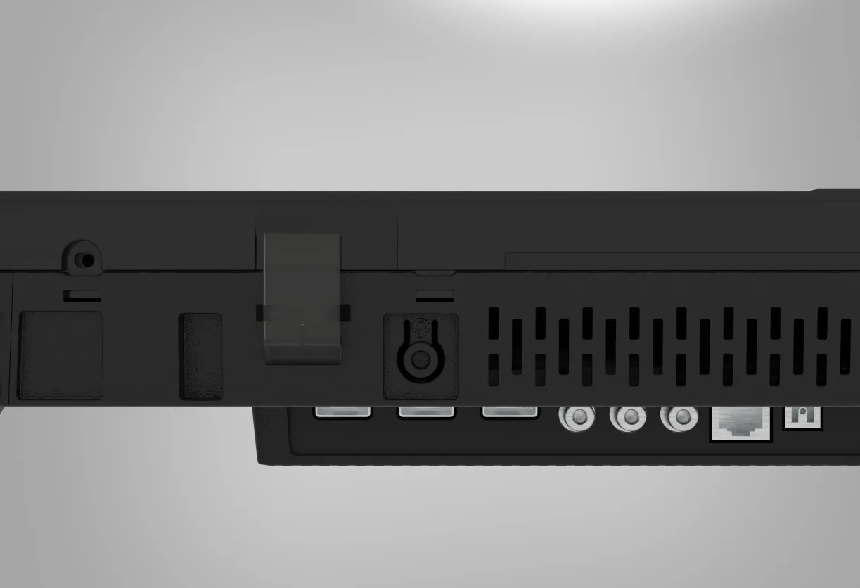
The cover shows a port area of an assembled unit in supplied company materials. It does not evidence a specific opening, a tolerance stack or an insertion result, and the recessed-port case is hypothetical. Cutout geometry must be confirmed against the approved connector, the mating plug, the board position and the actual assembly sequence.