
Article Snapshot
What this article covers
A vent pattern is where thermal intent, structural continuity, sheet-metal tooling and product safety meet. This guide sets out what each discipline must supply, how the pattern options differ and how to release the requirement without pretending to certify it.
- Give the opening pattern an owner and a stated purpose.
- Keep stiffening paths continuous around cutouts.
- Compare pierced holes, slots and formed louvers honestly.
- Separate thermal performance from safety compliance.
Ventilation openings look like the easiest feature on a TV back plate. A thermal engineer asks for more open area, a designer draws a row of holes, and the tool makes them. The difficulty appears later, when the panel handles poorly around the pattern, when burrs face the wrong side, when a clip no longer has material to sit on, or when someone asks whether the opening meets a safety requirement and nobody can answer without the full product configuration.
This guide treats the vent pattern as a structural feature and a cross-discipline interface. It covers what the thermal side needs to supply, how openings interrupt load paths, how pierced holes, slots and formed louvers differ, what the die and press must handle, and where the engineering responsibility stops and the brand owner's compliance process begins. It does not provide airflow values, temperature targets or safety limits, and the pattern table is a planning aid rather than a design standard.
1. Treat the opening pattern as structure and interface
Every opening removes material that was carrying load. On a large stamped panel the removed area is often small relative to the whole surface, so the immediate stiffness loss can look minor. The effect is local: the ligament between adjacent holes becomes a small column, the edge of the pattern becomes a stress riser, and the remaining material has to route force around the cutout field. Handling and assembly loads find those weak points quickly.
The pattern is also an interface. It sits between the thermal design inside the product and the environment outside it. It may need to admit air while limiting access to live parts, block a direct path to a hot component, avoid a cable route, clear a stand or wall bracket, and stay out of a cosmetic zone. Each of those constraints belongs to a different owner, and the drawing is where they must be reconciled.
Start by naming the owner of each constraint. Thermal performance belongs to the thermal or system engineer. Structural continuity belongs to the mechanical designer. Tooling feasibility belongs to the stamping supplier. Safety compliance belongs to the brand owner and the certification body acting on the full product. Writing this list down early prevents the pattern from being negotiated by whoever draws it last.
2. Define what the airflow owner must supply
A request for "more ventilation" is not an engineering input. The thermal owner should supply the region where airflow is needed, the direction of the intended flow, the components that must be cooled, the space available on both sides of the panel, and any acoustic constraint. They should also state what the pattern must not do: for example, provide a straight path to a specific component or create a whistle at an operating condition.
Open area is a useful summary but a poor specification on its own. The same open area can be distributed as many small holes or a few large slots, and the two behave differently structurally and acoustically. Ask for the distribution and the preferred orientation, not just a percentage. If the thermal team has a validated pattern from a previous platform, ask for the evidence that it transfers, rather than assuming that a similar-looking grille will perform the same way.
Agree how the pattern will be evaluated. A thermal simulation, a prototype test or a comparison with an existing product are different levels of evidence, and they support different decisions. The supplier can build the pattern; the supplier cannot confirm that the product meets a temperature target unless the program gives it a defined test and the authority to interpret the result. Keep that boundary explicit in the RFQ.
3. Keep load paths continuous around openings
The structural question is where force goes when it reaches the pattern. If a stiffening bead runs into a cutout and stops, the load must detour around the opening through whatever material remains. That detour is usually narrower, less supported and more prone to local bending than the original path. The result is a soft spot that shows up as handling damage, a wave in the cosmetic surface or a crack at a corner.
Design the pattern so the remaining ligaments form a coherent path. Align the pattern with the panel's main stiffening direction rather than cutting across it. Leave a margin between the outermost openings and the flange or bead, and keep that margin consistent. Where the pattern must cross a stiffening feature, interrupt the feature cleanly with a relief rather than letting the tool tear through it.
Pay attention to corners. A rectangular slot has four corners, and each is a stress concentration. A rounded end, a slot with a generous end radius or a staggered arrangement of shorter openings distributes the same open area across more, less severe transitions. This is ordinary sheet-metal practice, and it matters most when the panel is thin, large or subject to repeated handling.
4. Choose between pierced holes, slots and formed louvers
Three pattern families cover most television back plates. Pierced round holes are simple to tool, predictable in edge quality and easy to arrange in a grid. Slots remove more area per cut and can be oriented to suit flow, but they create longer unsupported ligaments and more demanding tooling. Formed louvers displace material to create a shield or a directional passage, which changes both the structural and the airflow behavior.
The choice is not about which looks best on a rendering. It is about the combination of open area, structural continuity, tooling cost, burr access and the direction in which air and fingers can travel. A louver may be preferable where a direct line of sight or access must be interrupted; a plain slot may be preferable where the panel needs to stay flat and the die should stay simple.
Planning comparison, not a design rule: the table summarizes the trade. The ratings are directional and must be confirmed for the actual panel, material and tool.
| Pattern | Structural effect | Tooling | Edge and burr | Airflow interface | Main risk |
|---|---|---|---|---|---|
| Pierced round holes | Moderate local weakening; predictable ligaments | Simple punches, easy maintenance | Clean edge, burr side controllable | Omnidirectional, limited open area per hole | Large hole count and die wear |
| Slots | Longer unsupported ligaments; direction-sensitive | Longer punches, higher load, wear risk | End radius and burr direction critical | Directional, higher open area per cut | Edge wave and corner cracking |
| Formed louvers | Adds local stiffness; displaces material | Forming station, more complex die | Formed edge, coating strain | Shielded or directional passage | Read-through and coating damage |
5. Control spacing, edge condition and burr side
Ligament width is the distance between adjacent openings, and it is the single most useful pattern dimension for structural review. A narrow ligament between two long slots is a small column in compression and a notch in bending. Set a minimum ligament that the process can hold and the structure can tolerate, and keep it consistent through the pattern rather than tapering it toward the edge.
Burr direction matters for three reasons: handling safety during assembly, appearance if the surface is visible, and fit if a mating part sits against the edge. The burr side is set by the tool direction, so it must be decided before the die is built. State it on the drawing in terms of the finished product, not in terms of the press stroke, and confirm that the assembly sequence does not expose the wrong face.
Edge quality also affects coating. A rough or torn edge holds less coating and can initiate corrosion, especially on galvanized sheet where the cut face is unprotected. If the part is painted or powder-coated, the coating bridge over a burr is thin. Deburring, a better die condition or a change in the cut direction may be needed, and each of those has a cost that belongs in the pattern decision.
6. Check the die and press implications
Every opening is a punch and a die opening, and the pattern determines how much work the tool must do in one stroke. A dense pattern of small holes needs many punches, a long slot needs a slender punch that is more vulnerable to wear and breakage, and a louver needs a forming station in addition to the cut. The press tonnage, the die structure and the maintenance plan all follow from the pattern.
Ask the tooling engineer whether the pattern can be produced in the intended number of stations. A pattern that requires an extra station may still be acceptable, but it changes the tool cost and the production layout. A pattern with very narrow ligaments may need a different punch material or a different clearance, and those choices affect burr, tool life and the risk of scrap sticking.
The die also constrains the pattern's position. Openings close to a bend line can distort during forming, and openings close to the edge can leave too little material for the flange. Review the pattern against the forming sequence, not only against the flat blank. A pattern that looks well spaced on the flat layout may be squeezed or stretched when the beads and flanges are formed.
7. Protect the opening from the assembly and service envelope
A vent pattern is a hole in the product's outer surface, so it interacts with everything behind it. A cable routed too close can block the openings or be abraded by a burr. A connector or a stand bracket can sit directly behind the pattern and reduce the effective open area. A service procedure that requires a tool to pass through the area can damage the panel or the components inside.
Check the pattern against the internal layout, not only against the external appearance. Mark the components and cables that sit behind the grille, and confirm that the pattern does not create a direct path to a hazard or a delicate part. Where a shield is needed, a louver or an internal baffle can provide it, but each adds cost and should be justified by a stated function.
Service access deserves its own review. If a technician must reach a component through the vent area, the pattern has to tolerate that access without sharp edges or a collapsed ligament. If the component is reached by removing the back plate, the pattern only needs to survive handling. Clarify which case applies before designing for the harder one.
8. Separate thermal performance from safety compliance
Thermal performance and product safety are related but not the same question. A pattern that improves airflow can also change the accessibility of live parts, the spread of fire from inside the enclosure or the ingress of foreign objects. A pattern that satisfies a thermal target has not thereby satisfied a safety requirement, and a pattern that satisfies a safety assessment has not thereby met a temperature target.
IEC 62368-1 is a product safety standard organized around energy sources and the safeguards applied to them; its public scope describes classification and protection, not a universal opening size. UL Solutions' public question-and-answer material notes that opening requirements depend on the specific configuration and that the standard does not prescribe a general number of openings. CSA Group's guide for the fourth edition notes that the effective opening size can change with wall thickness and with the angle of the opening, and that additional restrictions apply in some cases.
Those points support a simple working rule: the vent pattern must be reviewed against the actual product configuration, and the compliance conclusion belongs to the brand owner and the certification body. KINGSUN can manufacture a pattern, document its geometry and support the review with samples and measurements. KINGSUN does not certify the television, and a supplier statement that a pattern "meets the standard" is not a substitute for the product assessment. Ingress protection under IEC 60529 is a separate classification again, with its own test conditions.
9. Work through a hypothetical slot-pattern revision
Hypothetical planning example, not a KINGSUN customer case: a thermal review asks for more open area in a lower rear region, and the designer replaces a row of round holes with a small number of long slots. The open area increases, but the ligaments between the slots become narrow and the panel develops a visible wave along the lower edge after handling.
The team reviews the pattern against the support map and finds that the lower edge is already a relatively free span. Removing material there reduced the effective flange and left the edge with little resistance to bending. A second issue appears in the die review: the long punches increase the load per station and the tool needs more frequent attention.
The revised pattern groups shorter slots into three bands, keeps a wider ligament at each end and adds a shallow bead between the groups to restore continuity. The open area remains close to the thermal request, the edge regains stiffness, and the die returns to a more conventional punch layout. The lesson is that the pattern had to be designed with the structure and the tool, not chosen from an airflow sketch alone.
10. Put the requirement on the drawing and in the RFQ
The drawing should define the pattern precisely enough that two suppliers would produce the same part. Give the opening type, the position, the size, the end radius for slots, the ligament, the pattern extent and the burr direction. Reference the datum scheme used for position, and state whether the pattern is cosmetic, functional or both.
Add the non-geometric requirements that the pattern carries: the airflow function and its owner, any internal shield or baffle, the coating coverage expectation at cut edges, and the compliance route that the brand owner will follow. Do not write a safety conclusion into the drawing; write the requirement to support the review, and keep the conclusion with the party that is authorized to make it.
In the RFQ, include the panel material and thickness, the pattern drawing, the expected annual volume and the tooling model. Ask the supplier to comment on ligament width, punch layout, station count, burr control and edge coating. That response is where a manufacturable pattern emerges. The stamping DFM guide covers the broader feature review, the metal stamping process overview describes the production route, and the F02 series pages show representative rear configurations.
11. Sources and engineering boundaries
These references establish the scope of the standards discussed. They are not reproduced here, no clause numbers or limits are quoted, and none of them constitutes a compliance conclusion for a KINGSUN part or a customer product.
- IEC 62368-1:2023 — Audio/video, information and communication technology equipment: public scope covering energy-source classification and safeguards.
- UL Solutions — IEC 62368-1 questions and answers: opening requirements depend on configuration; the fourth edition revised fire-enclosure opening provisions.
- CSA Group — IEC 62368-1 Edition 4 guide: effective opening size varies with wall thickness and angle; Annex P adds restrictions.
- IEC 60529:1989+AMD2:2013 — Degrees of protection provided by enclosures: the IP classification is a separate assessment.
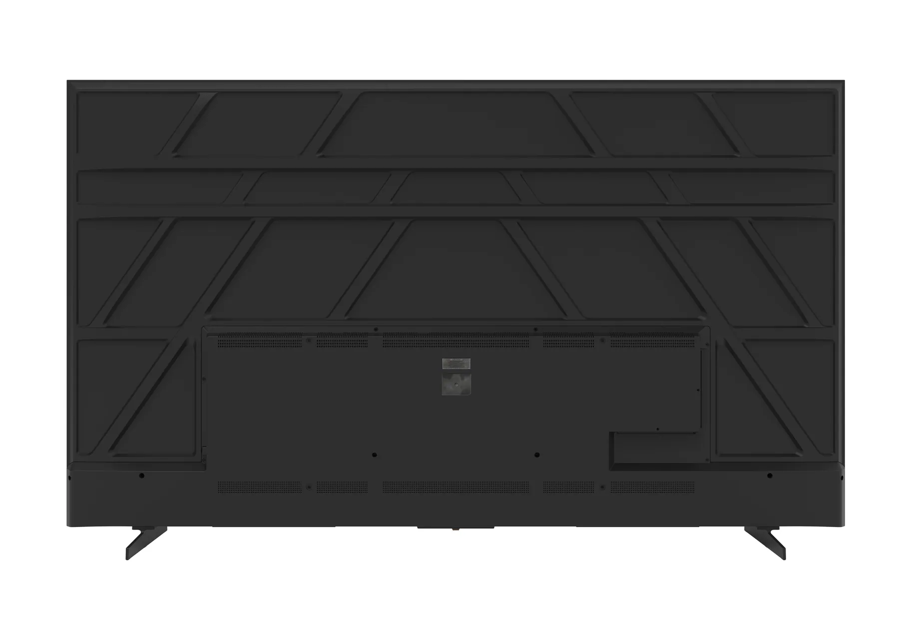
The cover shows the rear of an assembled television in supplied company materials. It illustrates a grille area and does not evidence airflow, temperature, acoustic behavior or safety compliance. The slot revision is hypothetical. Pattern geometry, structural effect and compliance must be confirmed for the actual product, and the safety judgment remains with the brand owner and the certification body.