
Article Snapshot
What this article covers
A die that still produces parts is not necessarily producing good ones. This guide connects part evidence, tool inspection, clearance control, scrap handling and repair records into a maintenance decision that a supplier and a customer can both review.
- Judge die condition against part requirements, not output alone.
- Track the wear mechanisms that change the part first.
- Measure clearance instead of assuming it stays as built.
- Record every repair as a configuration event.
A stamping die rarely fails suddenly. It wears, the clearance grows, the burr rises, the punch edge rounds, the scrap starts to lift, and the part drifts slowly enough that everyone accepts the newest normal. The press keeps cycling and the output number looks healthy. The evidence that something is wrong usually appears first in a measurement that nobody was plotting, or in a customer complaint that arrives months after the drift began.
This guide is about maintenance decisions during production, not about proving a new tool. It covers what die condition means for the part, the wear mechanisms worth watching, clearance as a controlled setting, inspection of the tool itself, protection of feed and scrap systems, the regrind or repair decision, and the records that make a repair traceable. It deliberately avoids universal intervals and cycle counts, because those depend on the die design, the material, the coating, the press and the part.
1. Define what die condition means for the part
Die condition is not an abstract measure of how old the tool looks. It is the ability of the tool to keep producing parts that meet the drawing, at the rate and quality the program requires. A die with visible wear can still make acceptable parts if the wear is in a non-functional area; a die that looks clean can produce a part with a burr that fails the next operation.
Start from the part requirements and work back to the tool features that produce them. The cut edge condition, the hole size, the bend angle, the formed feature depth and the flatness of a seating area are all tool outputs. Each has a feature in the die and a way it can degrade. Writing that map down turns maintenance from a general activity into a set of specific observations.
Include the downstream process. A burr that is acceptable on a bare part may be unacceptable after coating, because the coating bridges thinly over a sharp edge. A hole that is slightly small may still accept a screw but fail a connector. The definition of die condition therefore belongs to the same review as the finished-part requirements, not to the tool room alone.
2. Watch the wear mechanisms that actually matter
Cutting edges wear by abrasion, adhesion and chipping. Abrasive wear is gradual and shows up as a rounded edge and a larger effective clearance. Adhesive wear appears when material picks up on the punch or die and then tears away, leaving a rough edge. Chipping is local and sudden, often at a corner or a narrow punch, and it can produce a burr or a dimensional shift in a small area.
Forming features wear differently. A bead or a bend radius can polish, gall or develop a build-up that changes the local friction and the springback. A draw radius that wears can change the material flow and produce a split or a thinning that was not present when the tool was new. These are not cutting-wear problems and they need a different inspection approach.
Guide and locating elements also wear. Worn guide pins, bushings or locating pads let the strip shift, which changes the relationship between the pierce and the form. The part may still be within individual feature tolerances while the composite position drifts. This is one reason to inspect the tool's locating condition, not only the finished part's dimensions.
3. Treat clearance as a controlled, measured setting
Cutting clearance is the gap between the punch and the die opening, and it is usually expressed per side or as a percentage of sheet thickness. The right value depends on the material, its strength and its thickness, and it affects the cutting load, the edge quality, the burr and the tool life. A die built with a good clearance does not keep that clearance forever; it changes as edges wear and as the die is reground.
Dayton Lamina's technical article on die clearance makes the general point that the optimum depends on the material and thickness and that the wrong value affects load, hole quality and tool life. That is a toolmaker's perspective, not a universal table. The practical consequence for a television back plate program is that clearance should be a recorded setting, checked at build and rechecked after grinding, rather than an assumption that the tool retains its original geometry.
When clearance grows, the cut edge tends to show more rollover, a larger burr and sometimes a tear. When it is too tight, the load rises, the punch is more likely to chip and the die may pick up material. Both directions produce a part that can look acceptable in a quick visual check and fail in a measured one. Recording the actual clearance at each service interval is what makes the trend visible.
4. Inspect the die, not only the part
Part inspection tells you the result; die inspection tells you why. A maintenance review should include the cutting edges, the punch tips, the die inserts, the guide elements, the stripper and pressure pads, the scrap paths and the sensors. Each has a failure mode that may not show up immediately in the part.
Look for the physical evidence: a polished wear land on a punch, a rounded corner on a die insert, a smear of material on a forming radius, a loose guide, a cracked spring, a worn stripper plate. Photograph the condition and record the location. A photo taken at the same angle each time is more useful than a description, because it shows the rate of change rather than just the state.
Inspect the scrap. The shape and condition of the slug can reveal a clearance problem, a chipped punch or a stripping issue before the part shows it. A slug that is burred on both sides, or one that is consistently distorted, points to a cutting condition that needs attention.
5. Protect the die: scrap, strip feed, lubrication and sensors
Many die failures start with something that should not be in the tool. A slug that is not cleared can be pressed into the strip or into the die face, damaging a punch or an insert. A misfed strip can crash a pilot or a form station. A missing lubricant can cause galling and a sudden load increase. A sensor that is bypassed removes the protection that would have caught the problem.
Check the scrap path at every service. Confirm that the chutes are clear, that the slugs can fall freely and that the collection method does not back up during a long run. Confirm that the strip feed is consistent and that the pilot or locating feature engages before the work begins. Confirm that the lubrication reaches the areas that need it, especially the drawing and forming radii.
Sensors and interlocks are part of the maintenance scope, not an optional extra. A tonnage monitor, a strip-miss sensor, a slug detector or a part-out sensor only helps if it is working and if its signal is acted on. Record when a sensor is bypassed and why, and restore it before production resumes. A bypassed sensor is a maintenance debt that eventually gets paid with a crashed tool.
6. Decide regrind, repair or replace with evidence
The decision to regrind, repair or replace should follow from the condition and the requirement. Regrinding restores the cutting edge and changes the tool height, which then affects the shut height and the related forming stations. A local repair can restore a chipped corner or a worn insert without touching the rest of the tool. Replacement is appropriate when the wear is distributed, the tool has been ground repeatedly or the repair no longer holds the required geometry.
Before choosing, answer three questions. What is the measured condition of the feature? What part requirement does it affect? What is the consequence of another production run in the current state? A die with a slightly rounded edge in a non-critical area may run longer with monitoring; a die with a chipped punch near a connector opening may need immediate attention because the burr affects the interface.
After any regrind, the die is a different tool in a real sense: the shut height, the clearance and the forming depths have changed. Verify the first parts against the drawing and record the new tool state. Do not assume that a regrind restores the original condition exactly; it restores the cutting edge at the cost of some tool height, and the rest of the tool must be adjusted to match.
7. Treat every tool repair as a configuration event
A repair changes the tool that produces the part, even when the drawing does not change. If the repair is not recorded, the next investigation cannot tell whether a part was made before or after the change. Treat the tool repair as a configuration event: record the tool identifier, the date, the feature repaired, the before and after condition, the parts produced since the last service and the first-part verification.
This is the same discipline described in the engineering change control guide, applied to the tool rather than the drawing. The connection matters when a customer asks why a recent lot behaves differently. A repair record can answer that question in minutes; an undocumented repair turns it into a speculation.
Link the record to the production lots. If the repair changed a functional feature, the first lot after the repair deserves a check against the drawing and, where relevant, an assembly check. If the repair was purely cosmetic or preventive, the record can say so. The point is to make the distinction visible rather than to treat every repair as either trivial or catastrophic.
8. Use first/last piece and trend data to catch drift
A single good part at the start of a run does not prove the run is stable. A first-piece check confirms the setup; a last-piece check confirms the end condition. Together they bracket the run, and the difference between them is a signal. If the last piece is drifting toward a limit, the next run starts with a known risk.
Trend data is more useful than a pass or fail record. Plot the burr height, the critical hole size, the bend angle or the flatness of the seating area across runs. A slow trend is visible long before the value leaves tolerance, and it gives maintenance a chance to act on a planned stop rather than an unplanned one. The specific characteristic depends on the part; the principle is to choose the ones that the die can actually change.
Keep the measurement method consistent. If the burr is checked with a different instrument or at a different location each time, the trend is noise. Define the check, the location, the instrument and the operator qualification, and keep them stable enough that a change in the number means a change in the part.
9. Work through a hypothetical burr escalation
Hypothetical planning example, not a KINGSUN customer case: a back plate passes its dimensional check for three consecutive lots, but the burr height on one connector opening rises each time. The part still assembles, so the trend is not treated as urgent until a customer reports a cable jacket abrasion.
The review finds that the punch edge at that opening has rounded and the effective clearance has grown. The die has not been reground since the start of the campaign, and the burr was not part of the routine check. The part dimensions stayed within tolerance because the hole size changed only slightly; the burr changed much more.
The die is reground, the punch is replaced, and the first article is checked with the burr measurement included. The lesson is not that the die should have been reground on a fixed schedule; it is that the burr was a leading indicator that the program was not watching. Adding it to the trend check would have caught the drift before the customer did.
10. Set the maintenance record and the RFQ questions
A usable maintenance record has an identifier for the tool and the part, the service date and reason, the condition found, the work performed, the parts produced since the previous service, the first-part result and the person who released the tool back to production. It should be short enough to complete honestly and structured enough to compare across services.
Planning table, not a prescribed interval: the checks below are a starting structure. The frequency and the trigger values must come from the tool design, the material and the observed behavior.
| Check item | What to observe | Evidence | Trigger to define | Record |
|---|---|---|---|---|
| Cutting edge and punch tip | Rounding, chipping, pickup | Photo, wear land, burr sample | Burr or edge condition outside the agreed limit | Tool ID, location, action |
| Die insert and clearance | Gap change, wear pattern | Measurement at defined points | Clearance outside the recorded setting | Before and after value |
| Guides and locators | Play, wear, shift | Movement check, part position | Loss of repeatable location | Adjusted or replaced |
| Stripper and scrap path | Sticking, slug carry-over | Inspection, scrap sample | Any slug retention or misfeed | Cleaning or repair |
| Sensors and interlocks | Function, bypass status | Test at start of run | Any bypass without a plan | Restored and verified |
For an RFQ or a supplier review, ask how the tool is identified, how the maintenance record is kept, which characteristics are trended, how a repair is released back to production and what evidence accompanies the first lot after a service. The answers reveal whether maintenance is a system or a reaction. The tooling and mold manufacturing overview describes the build side, and the tooling trial guide covers the transition from a new tool to production.
11. Sources and engineering boundaries
These references support general tooling and asset-management concepts. They do not provide a maintenance interval, a die life or a clearance value for a television back plate.
- Dayton Lamina — A New Look at Die Clearance: clearance expressed per side or as a percentage of thickness; the optimum depends on material and thickness and affects load, edge quality and tool life.
- AIDA — Stamping Press Slide Guide Systems: slide guidance maintains punch and die alignment; equipment-maker background.
- ISO 55000:2024 — Asset management: vocabulary and principles for managing physical assets; used only as background for records and responsibility.
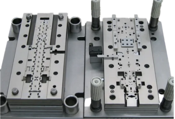
The cover shows an open die in supplied company materials. It does not evidence a maintenance interval, a tool life or a specific repair, and the burr escalation is hypothetical. Maintenance frequency, clearance values and acceptance limits must be established for the actual tool, material and part requirement.