
Article Snapshot
What this article covers
A television back plate rarely fails because a single screw was the wrong type in isolation. It fails, loosens, distorts, or becomes unserviceable because the joint was never described as a system: what it must hold, how it will be reached, what it will bear after assembly, and how it can be opened again without damage. This guide compares screwed joints, clinched joints, self-clinching inserts, and bonded supports on those terms, and states the information a supplier needs before any method can be confirmed.
- Describe each joint by load path, access, serviceability, and failure mode, rather than by fastener name alone.
- Identify where a permanent joint helps and where it creates a repair or tolerance problem.
- Separate a thread, a hole, a bearing surface, and a coating decision that are often confused in a drawing.
- Prepare a joint list for an RFQ that a supplier can review without guessing at loads, sequences, or service requirements.
Openings and joints are often discussed as if they were the same problem. They are not. The companion guide on connector cutouts and board interfaces deals with where openings go, what passes through them, and how edges and clearances protect the parts around them. This guide deals with what happens after the parts meet: how they are held together, how the holding force is created and maintained, and what happens when the assembly must be opened, adjusted, or repaired. A well placed opening can still sit in a poor joint, and a strong joint can still damage a housing if its bearing surface, sequence, or thermal behaviour was never checked.
1. Start from the joint, not the fastener
Begin with the job the joint must do, in plain language, before naming a screw, a clinch, or an insert. Is it structural, carrying load from a bracket or a hanging feature, or mainly a closure joint that keeps parts aligned and in contact? Must it resist separation, sliding, vibration, or a combination of those loads? Must it be opened in service, and if so, how often, with what tool, and with what risk to the surrounding part? A joint that is never opened can accept permanence. A joint that protects a board, a cable, or a replaceable module cannot, unless the service plan explicitly accepts replacing a larger assembly when that joint is disturbed.
Next, name the failure that would matter first. For a screwed joint, it may be loss of clamp load, thread stripping in thin or soft material, or bearing damage under the head. For a clinched joint, it may be separation under peel load, or damage to a coating or a nearby formed feature. For a bonded support, it may be gradual loss of adhesion after heat, moisture, or contamination. Each failure points to a different check: clamp and friction for a screw, sheet behaviour and tool access for a clinch, and surface preparation and service environment for a bond. If the failure mode is not named, the test that follows will usually test the wrong thing, and a passing result will create false confidence.
2. Map every interface before choosing a method
A television structure contains more interfaces than its bill of materials suggests. The back plate meets internal brackets, board mounts, grounding points, and covers. The rear housing meets the back plate, bezels, stands, and service covers. Each meeting point has its own materials, thicknesses, finishes, and tolerances, and a method that suits one interface may damage another. Mapping the interfaces first prevents a method from being copied across the assembly simply because it worked at the first location where it was tried.
For each interface, record the two materials and their relative hardness and stiffness, the thickness of each layer, the finish or coating on each surface, and the space available on both sides. A screw needs a bearing surface and a thread or nut on the other side. A clinch needs tool access and a controlled gap between the sheets. A self-clinching insert needs a correctly sized hole and a sheet that can flow around it. A bonded pad needs a clean, flat, and accessible area. If any requirement cannot be met at a location, that location needs a different method, a local design change, or a deliberate exception with a stated reason. It should not inherit a method by default.
3. Screwed joints: control, service, and thread risk
Screwed joints remain the most controllable option when a joint must be opened, adjusted, or replaced, because clamp load can be created, checked, and recreated. That control depends on more than the screw itself. The thread, the bearing surface, the friction condition, and the tightening method together determine how much applied torque becomes useful clamp load and how much is lost to friction. Lubrication, plating, coating, and surface condition change friction, so a torque value correct for one surface condition may be wrong for another. Torque, preload, and any locking feature must therefore be treated as specification-dependent values for the actual fastener, material, finish, and tightening method, never as universal values copied from another programme.
Thread engagement is the second control point, and it matters most in thin sheet. A screw engaging only a few threads in a thin back plate, or threading directly into a soft molded boss, can strip before it reaches the intended clamp load. The remedy is not always a larger screw. It may be a nut, a captive nut, a self-clinching insert, a thicker local boss, or a change in geometry that spreads the load. Each remedy changes the part, the tool, or the service path, so the choice belongs in the joint review, not in a late assembly workaround. Thread-forming screws in molded housings raise a related question: boss design, screw specification, and the number of permitted reinsertions must be agreed together, because repeated removal can wear a plastic thread never designed for repeated service.
4. Clinching and formed joints: permanence with a price
Clinching joins sheet metal by forming the sheets together into a mechanical interlock, without an additional fastener and usually without heat or a separate joining material. That simplicity is attractive for large, repetitive structures: there is no loose fastener to drop, no thread to strip, and no separate nut to align. Published manufacturer background on clinching for thin sheet in appliance housings describes the same practical appeal, while also showing that fit-up and alignment strongly affect clinch quality. In other words, the joint is only as repeatable as the parts that enter it and the tool that forms it. A clinch cannot correct a gap, a misaligned hole, or a distorted edge that should have been controlled earlier.
Permanence is the price. A clinched joint is not designed to be opened and remade in service, so it should not be used where a board, a cable, or a module behind the joint will need replacement, unless the service plan accepts a larger replacement or a different access route. Peel and prying loads also deserve attention, because an interlock that resists shear well may behave differently when one sheet is lifted away from the other. Joint geometry, sheet combination, and tool must therefore be reviewed together, and any claim about strength must be tied to the actual sheets, thicknesses, and test method for the programme. A general statement that clinching is strong, without those conditions, is not a design input.
5. Self-clinching inserts: threads in thin sheet, with limits
Thin sheet presents a familiar problem: it is too thin to carry a useful thread on its own, yet the assembly needs a repeatable threaded connection. Self-clinching inserts address that problem by being pressed into a correctly sized hole so that the surrounding sheet cold-flows around the insert and locks it in place. Manufacturer installation guidance for this family stresses a properly sized mounting hole, parallel punch and anvil surfaces, and a squeezing force that seats the insert flush, with displaced metal locking the insert against rotation and pull-out. The key condition is hardness: the insert must be harder than the sheet it is installed into, so the sheet, rather than the insert, flows during installation. That condition must be checked for the actual material combination, not assumed from a catalogue description.
The limits are equally important. A self-clinching insert provides a thread, but it does not by itself guarantee clamp load, bearing condition, or corrosion compatibility. The mating screw, washer or bearing surface, coating, and tightening method still need to be specified together. Edge distance and hole position matter, because an insert too close to an edge, a bend, or another feature can distort the sheet or weaken surrounding material. Installation also needs access and a controlled press operation; an insert installed by hand or on an uneven surface may look seated while its locking feature is only partly engaged. Inspection should therefore check seating and alignment, not only the presence of the insert.
6. Bonded supports: useful help, not a silent substitute
Adhesives and tapes can be useful in television structures, but their role should be stated precisely. A bonded pad can distribute load, damp vibration, support a stiffener, or hold a trim or cover in position. It can also reduce visible fasteners and avoid a hole through a finished surface. Manufacturer background on structural foam tapes describes them as an alternative to screws, rivets, or welds in suitable panel and trim applications, with adhesion depending on substrate, surface preparation, and service environment. The lesson for a television structure is not that bonding replaces mechanical joining everywhere, but that it earns its place only where its load path, surface, and environment are understood.
The risks are quieter than those of a screw or a clinch. A bond can look complete while adhesion is weak because the surface was oily, dusty, painted with an incompatible finish, or too cold during application. Peel loads, long-term heat, moisture, and creep can reduce a bond that passed an initial handling check. A bonded joint carrying a structural load therefore needs a defined substrate, surface preparation, application pressure and dwell condition, and an agreed inspection or test method. If none of those can be stated, the bond should be treated as a positioning or support aid, with a mechanical joint carrying the load, rather than as the primary load path.
7. Joining metal to a molded housing without forcing the weaker side
Metal-to-plastic joints deserve a separate review because the two sides fail in different ways. Steel can tolerate a concentrated bearing load that would crack, creep, or whiten a molded boss. A molded housing can tolerate a distributed, well supported load that would be trivial for steel. When a screw is tightened directly into a plastic boss, boss design, screw type, bearing washer, and torque condition must be agreed as a set. Overtightening can crack the boss immediately or create residual stress that fails later. Undertightening can leave the joint loose under vibration or handling. Neither outcome is a fastener problem alone; both are joint design outcomes.
Thermal behaviour adds a second difference. Metal and molded plastic expand at different rates, so a joint tight at room temperature may lose clamp load or gain stress as the assembly warms and cools in service. Long-term creep in plastic can also reduce clamp load over time, even without a temperature cycle. Those effects cannot be resolved by choosing a stronger screw. They are resolved by joint geometry: a larger bearing area, a metal insert or a through-bolt with a nut where service allows, a controlled torque and tightening sequence, and a boss and rib design that spreads load rather than concentrating it at a single point. Where a metal insert is used, its retention, its effect on molding, and its service behaviour must be reviewed with the housing design, not added as a late fix.
8. Sequence, access, and tolerance: where assembly fails in practice
Many joining problems are sequence problems. A joint easy to form on a bench can become impossible when parts are already assembled, when a tool cannot reach it, or when an earlier joint has already locked the assembly into a distorted position. The assembly sequence should therefore be reviewed joint by joint: which joint is made first, which joint locates the parts, which joint only clamps them after location, and which joint must remain loose until a later adjustment is complete. A locating joint and a clamping joint have different jobs, and confusing them is a common source of forced assembly, in which parts are pulled together by screws rather than located by their features.
Access is the practical side of sequence. Tool clearance, driver angle, hand clearance, and the path for inspection must be checked in the assembled state, not only on a single part drawing. A screw reachable only after a board is removed, a clinch needing a tool on both sides where only one side is accessible, or an insert that must be pressed before a bend is formed, all create the same outcome: rework, damage, or an unmade joint discovered late. The sequence review should also state the tightening order for multi-fastener joints, so parts seat evenly rather than being pulled to one side. A systematic bolted-joint guideline such as VDI 2230 treats assembly preload, its scatter, embedding, and thermal change as part of the joint calculation, which is a useful reminder that tightening is a process with variation, not a single number on a drawing.
9. Work through a hypothetical joint comparison
Hypothetical planning example, not a KINGSUN customer case: a team is reviewing a bracket that fixes a board support to a metal back plate, with a service cover nearby. The bracket must be removable when the board is serviced, the back plate is thin, and the bracket sits close to a ventilation opening. Three routes are considered: a screw into a self-clinching insert, a clinched joint, and a bonded pad with two locating screws.
The clinched route is rejected first, not because clinching is weak in general, but because this joint must be opened in service. A permanent joint would force replacement of a larger assembly or a different service route, and neither has been agreed. The bonded route is also set aside as the primary load path, because the bond area is close to the ventilation opening, the surface finish at that location is not yet fixed, and the service requirement means the bracket must be removed and refitted cleanly. Bonding could still support the bracket or damp vibration, but it cannot be the joint that the service plan relies on.
The remaining route, a screw into a self-clinching insert, fits the stated needs, but only with conditions attached. The insert must be specified for the actual sheet material and thickness, the hole must be correctly sized and positioned away from the ventilation edge and the bend, and the mating screw, bearing surface, and tightening condition must be agreed together. The tightening sequence must seat the bracket evenly, and the service procedure must state permitted removals and inspection after refitting. The lesson is not that one method wins in general. It is that the service requirement, the thin sheet, and the nearby opening together eliminate two routes, and the surviving route still needs a complete joint description before it can be approved.
| Joining method | Best fit in this guide | Serviceability | Main risk to control | Information needed before approval |
|---|---|---|---|---|
| Screwed joint with nut or insert | Joints that must be opened, adjusted, or replaced | High, if thread and torque conditions are agreed | Loss of clamp load; thread damage in thin or soft material | Fastener and thread specification, bearing surface, friction and tightening condition, service limit |
| Clinched joint | Permanent metal-to-metal joints with good tool access | Low; not designed for repeated opening | Peel load; poor fit-up or alignment; coating or edge damage | Sheet combination and thicknesses, tool access, joint geometry, test method for the actual sheets |
| Self-clinching insert | Threaded connection in thin sheet | High for the mating screw, if the insert remains intact | Wrong material combination; poor hole size or seating | Insert type, sheet material and thickness, hole condition, edge distance, installation method |
| Bonded support | Load distribution, stiffening, trim, or cover support | Low to moderate; removal may damage the bond or surface | Weak adhesion from surface, finish, heat, or moisture | Substrate and finish, surface preparation, application condition, service environment, inspection method |
| Rivet or other formed joint | Permanent, inspectable joints with access on both sides | Low | Bearing damage; hole and head interference | Hole and bearing condition, head clearance, inspection method, service plan |
10. Use the joint list in the RFQ
A joint list turns this guide into a reviewable RFQ input. It should be a short table or schedule, not a narrative, and it should travel with the drawing. For each joint, state the two parts, the joining method, the load direction and service requirement, the materials and thicknesses, the hole or boss condition, the bearing surface, and the tightening, installation, or bonding condition where applicable. State what is still open, and who owns the decision. A joint list that hides an open question behind a familiar fastener name will return as rework, because the supplier will have to guess at the missing condition.
The RFQ should also ask the supplier to comment on sequence and inspection, not only on the joint itself. Which joints locate the assembly, which joints are made first, which joints need tool access that the current design does not provide, and how will each joint be inspected after assembly? Those questions reveal whether the joining plan is buildable, and they give the supplier a clear way to propose a change without redesigning the product. A supplier comment that a clinch cannot be reached, or that a boss will crack at the proposed torque, is valuable early, and it is far cheaper than the same comment after tooling.
Finally, keep the joint list under change control with the drawing. When a material, finish, thickness, or service requirement changes, recheck the affected joints, even if the fastener name stays the same: no joint is approved by its name, but by its load, materials, sequence, and service plan, stated together and confirmed for the actual parts.
11. Sources and engineering boundaries
These references support general joining concepts only. They do not provide a torque, strength, or durability value for any KINGSUN part, and no value in this article should be used as a design limit for a specific programme.
- ISO 898-1:2013, Mechanical properties of fasteners made of carbon steel and alloy steel, Part 1: Bolts, screws and studs — scope and property-class background. The standard's published scope notes that it does not specify torque and clamp-force performance; that performance is a separate, specification-dependent question. https://online.standard.no/en/iso-898-1-2013-2
- VDI 2230 systematic calculation of highly stressed bolted joints — background on assembly preload, preload scatter, embedding, and thermal change as parts of a joint calculation, not as a single torque figure. https://www.eassistant.eu/fileadmin/dokumente/eassistant/etc/HTMLHandbuch/en/eAssistantHandbch14.html
- PennEngineering self-clinching fastener installation guidance — properly sized hole, parallel punch and anvil, flush seating, and the hardness condition that the insert must be harder than the sheet. https://www.pemnet.com/kr/wp-content/uploads/sites/2/2022/06/fdata.pdf
- TOX Pressotechnik clinching background, via ASSEMBLY Magazine — clinching of thin sheet, and the practical importance of fit-up and alignment for clinch quality. https://www.assemblymag.com/articles/99712-appliance-maker-clinches-stainless-steel-sheets
- 3M VHB architectural panel tape background — foam-tape bonding as an alternative to mechanical fasteners in suitable panel and trim applications, with adhesion depending on substrate and surface condition. Background only; not a claim about television housings. https://www.3m.com/3M/en_US/p/d/v000238819/
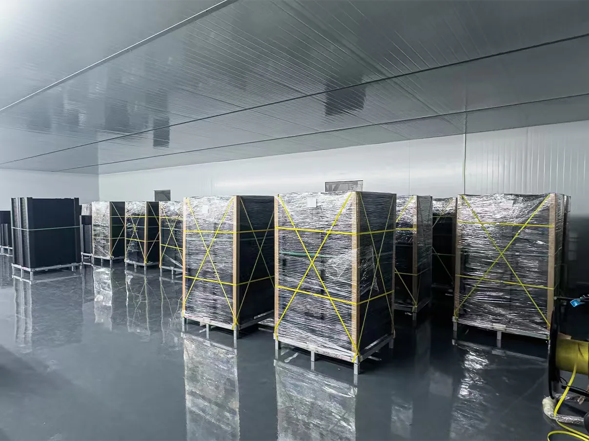
The cover shows finished back plates in supplied company materials. It does not evidence a specific joint, fastener, installation, or qualification. The comparison in section 09 is hypothetical, and every joint must be confirmed from the actual drawing, materials, finishes, sequence, service requirement, and approved specification for the programme.