
Article Snapshot
What this article covers
A first sample that fits on a bench can still fail in assembly, drift across a production run, or hide a tool correction that was never revalidated. This guide helps you decide whether a mold is ready for production release, what evidence to ask for at each gate, how to judge a trial, and what must trigger a new validation round.
- Decide which inputs must be frozen before steel is cut.
- Decide which tool choices affect stability and maintenance.
- Decide what a trial must measure, not merely demonstrate.
- Decide when a correction requires revalidation.
- Decide what to put in an RFQ so validation is a shared plan rather than a late argument.
1. What validation must prove
Validation is often confused with sampling. Sampling produces parts. Validation proves a process can repeatedly produce conforming parts. The conditions must be documented and repeatable. A single good sample proves very little. It says nothing about cavity variation. It says nothing about the process window edges. It says nothing about a changed material lot, machine, or operator.
A useful validation separates three questions. Is the tool built as designed? Does the process produce parts meeting dimensional and assembly requirements? Is that process robust against ordinary variation? A mold can pass the first question and fail the second. A gate can create a weld line in a stressed rib. Uneven cooling can distort a flat face. A narrow process can pass once and fail on the next shift.
For TV parts, assembly is the decisive test. A housing must mate with the back plate, boards, and fasteners without forcing the fit. Record what was accepted, and what change requires a new check.
2. Freeze the design inputs before steel is cut
Most expensive mold corrections begin as unmade decisions. Wall thickness varies without reason. A rib is too thick for its wall. A boss sits where cooling cannot reach it. A cosmetic zone is never defined. A datum scheme is left for the inspector to invent. Each can be fixed in design at low cost. Once steel is cut, the same change may require welding, re-machining, or a new insert. It may also disturb a neighbouring feature.
A frozen input set should be agreed before tool design begins. It includes part geometry and revision. It includes material grade and supplier data for shrinkage. It includes critical dimensions and datums. It includes cosmetic and non-cosmetic zones. It includes gate and ejector restrictions, assembly interfaces, and the acceptance method. Shrinkage depends on material, wall thickness, process conditions, and geometry. It must come from the material supplier's data for the chosen grade. It must be treated as an assumption to be confirmed by trial, not as a universal constant. Borrowing a value from another material or part builds the first error into the cavity.
Manufacturability review belongs at this stage. It must confirm filling, ejection, cooling, and function-based tolerances before steel is cut. Record agreed inputs and open items in writing.
3. Choose the tool architecture for the part, not for the press
Tool architecture is a set of trade-offs. Each choice should be justified by the part, not by habit. Cavity count affects output, balance, and variation. A multi-cavity tool can lower piece cost at volume. It also multiplies variation. Cavity dimensions, gate balance, cooling balance, and ejection can differ from cavity to cavity. For a large TV housing, a single-cavity tool is often the more controllable starting point. That is a judgement for the specific part, volume, and machine, not a rule. The RFQ should ask how cavity-to-cavity variation will be measured, whatever the count.
Gate selection is similarly consequential. The gate controls fill pattern, weld-line position, packing, and the mark left on the part. A gate placed for convenience may fill the part but place a weld line across a stressed rib or cosmetic face. A gate placed for appearance may create a long flow path demanding high pressure and leaving a thick section under-packed. The design review should show the intended fill pattern and its effect on features that matter. It should be supported by flow analysis where the part is large or complex. Flow analysis does not guarantee a good part. It makes the gate decision visible before steel is cut.
Cooling, venting, and ejection complete the architecture. Even cooling, clean venting, and balanced ejection protect flatness and shape. Record runner and moving-element choices with their maintenance needs.
4. Build and inspect the tool before the first trial
Tool build is where design intent becomes steel. Inspection at this stage prevents trials from testing a tool that was never built as drawn. The build record should include steel or insert material and its certificate where the specification requires it. It should include machining and finishing operations. It should include dimensional checks on cavity, core, slides, and inserts. These checks do not prove the part will be good. They establish a baseline. If a later part is out of tolerance, the team can ask whether tool, process, or material caused it, rather than guessing among all three.
Spotting and fitting deserve attention that is easy to skip under schedule pressure. Parting line, shut-offs, slides, and inserts must close and move as designed. They must do so without flash paths or interference. A tool that flashes will produce parts needing trimming and may hide a dimensional problem. A slide that does not seat fully will produce a step or short shot in a local feature. These are tool problems, not process problems. They should be found by inspection and dry cycling before resin is introduced. A trial beginning with a fitting problem generates data about that problem, not about the process.
Surface finish should be specified by zone, not by one grade for the whole tool. Cosmetic, hidden, and mating faces have different requirements. Judge them against an agreed standard, and record the tool baseline for maintenance.
5. Plan trials as experiments, not demonstrations
A trial is often treated as a demonstration. Run the mold, collect parts that look acceptable, and declare the tool ready. A validation trial should be planned as an experiment. Before the first shot, the team should agree on questions the trial must answer. It should agree on settings to be tested, parts to be measured, and criteria for a pass, a correction, or a further trial. Without that plan, a trial can succeed by accident. It can fail to reveal the narrow window that will cause trouble in production.
The usual sequence, often labelled T0 and T1, is useful shorthand. Labels alone prove nothing. The first trial typically checks that the tool fills, ejects, and produces a complete part. It reveals gross problems in gating, venting, cooling, or ejection. Later trials should test the process, not merely repeat the first success. They should include parts at intended centre settings and at edges of the proposed window. The team can then see whether a small change in melt temperature, injection speed, holding pressure, holding time, cooling time, or mold temperature moves a critical dimension out of tolerance. A tool that only works at one narrow setting is not ready, even if that setting produced a good sample.
Sampling discipline matters as much as machine settings. Identify parts by cavity, trial, and setting, and measure them under drawing conditions. Record defects as well as good parts.
6. Measure first articles against the drawing, not against appearance
First-article inspection is the gate where the drawing, not the eye, decides. It should compare every dimension the drawing calls out. It should pay special attention to critical dimensions affecting assembly, function, or fit. It should use a method capable of measuring the feature. A caliper spot check cannot replace a coordinate measuring machine report for a large housing with flatness, position, and profile requirements. A visual check cannot replace a dimensional check for a feature hidden after assembly. The method must fit the tolerance.
Tolerance frameworks can help buyer and supplier agree on what general tolerance means when the drawing does not call out every dimension. ISO 20457, for example, provides tolerances and acceptance conditions for plastic moulded parts. It uses datum systems and geometrical tolerancing concepts. It is a framework to agree on, not a substitute for the drawing. If the drawing specifies a tighter tolerance, the drawing governs. If the drawing is silent, the agreed framework should be named in advance. The first-article report can then be judged against a standard both sides accepted before the trial.
Appearance inspection needs the same discipline. Judge cosmetic zones against an agreed sample or standard, and record results by zone. Material and lot records belong in the same gate.
7. Establish a process window, then judge capability
A process window is the range of settings within which the part remains conforming. It is established by testing, not by declaring a centre point. The common approach, described in scientific molding guidance, is to use designed experiments. Those experiments find which parameters actually drive critical dimensions and defects. The team can then define a window around settings that keep those outputs in tolerance. Parameters most often tested are melt temperature, injection speed, holding pressure, holding time, cooling time, and mold temperature. Supporting conditions such as drying and mold temperature control should also be documented. The point is not to test everything. It is to test what matters for this part and document the result.
Once a window is proposed, capability should be judged against it, not against a single successful run. That means producing parts across the window, across cavities, and across normal production variation, such as material lots and machine setups, and measuring critical dimensions. If the part stays in tolerance across that variation, the process is robust. If it stays in tolerance only at the centre, the window is too narrow. The team then faces a choice: widen the window by correcting the tool, tighten process control, or revise the tolerance with the design owner's agreement. None of those choices should be made silently by narrowing inspection.
Statistical language should be used carefully. Agree the capability method and sample size before the trial. Write the resulting window into the production control plan.
8. Correct the tool in a controlled loop
Almost no large mold is right on the first trial, and a correction is not a failure. The failure is an uncontrolled correction. A controlled loop has four steps: diagnose the cause, propose the change, implement it, and revalidate affected features. Each step should be recorded. Revalidation should cover not only the corrected feature but also neighbouring features the change could disturb. Welding a rib, polishing a face, moving a gate, or changing a cooling channel can each shift another dimension. A correction fixing one feature while breaking another is not progress.
Change control connects this loop to the drawing and to sample approval already granted. If a correction changes a dimension, cosmetic zone, or assembly interface, drawing revision, sample status, and validation status must be considered together. The companion engineering change control guide covers the general discipline. For molds, the practical point is that a tool change without a drawing or sample decision creates two versions of the truth. The tool says one thing, the paper says another, and production follows whichever is easier to find.
Revalidation triggers should be agreed before production, not invented after a problem. Tool modification, insert replacement, major repair, a change of resin grade or supplier, a change of machine or auxiliary equipment, and a long period out of production are all reasonable triggers. The list must be specific to the program.
| Validation gate | What it must prove | Evidence to ask for | Failure if skipped |
|---|---|---|---|
| Design freeze | Inputs and cosmetic zones agreed | Frozen input list, open-item log | Steel cut around an open decision |
| Tool build inspection | Tool matches design and moves correctly | As-built checks, spotting notes | Trials test a fitting problem |
| First trial (T0/T1) | Tool fills, ejects, and reveals gross issues | Trial plan, settings, defect log | A sample hides a narrow process |
| First-article inspection | Parts conform by zone and method | Dimensional report, material record | Appearance passes, assembly fails |
| Process window and capability | Parts stay in tolerance across variation | Experiment summary, window, sample | Production drifts with setting or lot |
| Production release | Window, control plan, and triggers written down | Control plan, revalidation trigger list | A repair becomes an undocumented experiment |
9. Hypothetical case: a housing that passed the bench and failed assembly
Hypothetical planning example, not a KINGSUN customer case. A team develops a molded rear housing for a television program. The first trial produces parts that look clean. The outer face is smooth. Ribs appear complete. Hand measurement of overall length and width matches the drawing. The team is tempted to approve the tool and move to production.
A first-article check against the full drawing tells a different story. The mounting face that registers to the metal back plate is not flat within the required profile, because cooling is uneven across a large flat area. Two fastening bosses are in position in the plane of the face but sit at slightly different heights, so the housing rocks when screwed down. A connector opening clears the connector itself but leaves insufficient clearance for the cable bend once the board is fitted. None of these failures is visible on a bench sample. None is captured by overall length and width.
The correction loop addresses causes in order. Cooling is rebalanced, boss heights are corrected in the tool, and the opening is reviewed with the full assembly. The tool is ready only when those corrections are revalidated.
10. Use the validation record in the RFQ and at production release
Validation should be planned in the RFQ, not added after the tool is ordered. The RFQ can state design inputs the buyer will supply. It can state material and shrinkage basis, critical dimensions and datums, cosmetic zones and reference samples, trial and first-article plan, process-window method, and revalidation triggers. It can also state who owns the tool, who pays for corrections caused by design change versus tool error, and how sample approval will be recorded. Those commercial points are outside technical validation, but they determine whether a technical correction can be made without a commercial dispute. A validation plan without an ownership and correction agreement is incomplete.
At production release, the record should be short enough to be used and complete enough to be audited. It should contain accepted drawing revision, accepted material and lot basis, tool as-built baseline, trial and first-article results, process window and control plan, maintenance baseline, and revalidation triggers. It should also contain open items, if any, and conditions under which production may proceed despite them. A release with hidden open items is not a release. It is a postponement of the same argument to a worse moment.
Production monitoring should follow the same logic as validation. Critical dimensions should be checked at a planned frequency, by cavity where variation matters, and results compared with the window, not only with the tolerance. A trend toward a limit is information, even if the part is still conforming, and it should trigger investigation before it triggers scrap.
11. Sources and engineering boundaries
These references support general concepts in this guide. They do not supply a KINGSUN value, a tolerance for a specific part, or a guarantee for any program. Every dimension, material, and acceptance criterion must come from the approved drawing and specification for that program.
- ISO 20457:2018, Plastics moulded parts — Tolerances and acceptance conditions: a framework for moulded-part tolerances and acceptance conditions, used here only as a reference to agree on when the drawing does not specify a dimension. Description verified via https://meganorms.com/st-iso-20457-2018.html
- Scientific molding guidance, Kaysun: data-driven molding using flow analysis, designed experiments, and cavity-pressure monitoring to define a repeatable process window. https://www.kaysun.com/what-is-scientific-molding
- Injection molding process validation guidance, ZetarMold: distinction between mold qualification and process validation, and the critical parameters that most often control part quality. https://zetarmold.com/injection-molding-process-validation-complete-guide-for-engineers/
- Injection mold acceptance guidance, ZetarMold: trial as the definitive acceptance test, mold-flow analysis before steel is cut, and the limits of visual surface judgement. https://zetarmold.com/injection-molds-acceptance-criteria/
- Injection mold tooling best practice, Guardmans: toolmaking accuracy, spotting and fitting, documentation, T1 sampling, and establishing a process window. https://www.guardmans.com/Injection-Mold/best-practices-for-injection-mold-tooling-trusted-manufacturer.html
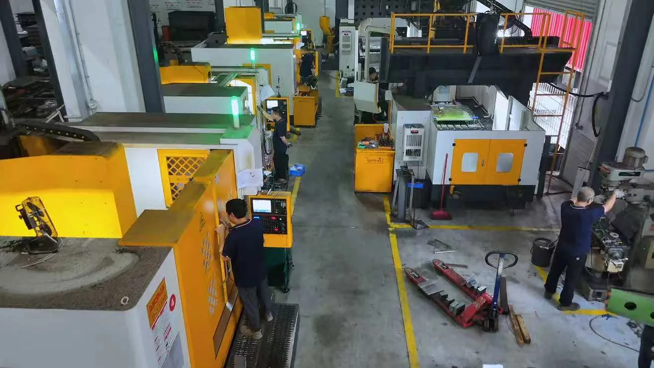
Boundaries. The cover shows tooling machines in supplied company materials. It does not evidence a specific mold, trial, or qualification. The hypothetical case in section 09 is invented for planning only and is not a KINGSUN customer project. No customer, certification, test result, KINGSUN measured value, universal design limit, capacity figure, OEE value, price, or inventory claim is made in this article. Validation is a gate based on the approved drawing and specification, not a guarantee that any future production run will conform without monitoring and maintenance.