
Article Snapshot
What this article covers
The problem is familiar: every individual feature looks acceptable, yet the back plate, the housing, the panel assembly and the fasteners do not come together cleanly, or they come together only after force, rework or a change that was never approved. Tolerance is often blamed at that point, but the real gap is usually earlier, in how the assembly requirement was translated into drawing limits, datums and an inspection plan.
- Separate a single-part dimension from an assembly requirement, and name the interface that actually decides fit.
- Read datums, form, orientation and location controls as a single system, rather than as unrelated notes.
- Build a simple tolerance stack-up, and know when a worst-case view and when a statistical view is the honest one to use.
- Ask for an inspection result that proves the assembled condition, not only the condition of a part lying free on a bench.
1. Start from the assembly, not from the single part
A television structural part rarely fails alone. It fails in relation to something else: a mating housing, a panel assembly, a bracket, a board interface, or a fastener pattern that must line up at the same time. A tolerance review should therefore start by naming the assembly, not by opening the part drawing at a random feature. Ask what must close, what must clear, what must stay aligned, and what must not be forced. A gap meant for assembly clearance is not the same as a gap that reveals a misaligned hole, and a tight joint in one corner is not proof that the whole perimeter is correct.
Once the assembly requirements are named, each one can be traced back to the features that control it. A mounting face may control seating, a hole pattern may control location, a formed edge may control clearance, and a flatness control may control how the part sits before any fastener is tightened. If a requirement has no feature that controls it, the drawing is incomplete for that requirement, even if every dimension on the sheet carries a tolerance. Tightening every limit because one interface is critical pays for precision where it adds no assembly value.
2. Say what kind of variation you mean
Size, form, orientation and location are different kinds of variation, and they fail in different ways. Size controls how large a feature is. Form controls how much that feature deviates from its ideal shape, for example how flat a surface is, regardless of where it sits. Orientation controls the angle of a feature relative to a reference, such as whether a face is parallel or perpendicular to a datum. Location controls where a feature sits relative to other features. A part can be the right size and still fail on form, orientation or location, and a drawing that only controls size leaves those failures unowned.
Geometric dimensioning and tolerancing, commonly called GD&T, provides a shared language for these controls. ASME Y14.5 establishes symbols, rules, definitions and recommended practices for stating and interpreting dimensioning and tolerancing on engineering drawings and related documents, and it treats form, orientation and location as distinct controls rather than as a single idea of accuracy. The ISO geometrical product specification system, including ISO 1101 for geometrical tolerancing, organises the same family of ideas into form, orientation, location, profile and runout controls. The two systems are not interchangeable in every detail, so the drawing must state which system governs. General tolerances need the same clarity: a title-block class, such as an ISO 2768 class for linear and angular dimensions without individual indications, governs every untoleranced dimension on the sheet, and changing it changes the meaning of those dimensions.
3. Choose datums that match how the part is assembled
A datum is a theoretically exact reference from which other features are located and measured. In practice, a datum system should mirror how the part is held, seated and fastened in the assembly. If the assembly seats on a mounting face and locates from two holes, a datum system that references an outer edge that never touches anything will produce measurements that are difficult to relate to the assembled condition. The part may measure well against an irrelevant reference and still assemble badly.
A useful datum review asks three questions. First, which feature actually seats the part, and is it the primary datum? Second, which features actually locate it, and do they appear as the secondary and tertiary datums in the order in which they constrain the part? Third, can the inspector reproduce that seating and location in a fixture or measurement setup without forcing the part into a shape it does not take in the assembly? If the answer to any of these is no, the datum system should be questioned before any tolerance value is debated. Datum choice also affects accumulation: dimensioning every feature from a single distant datum can stack variation along a long chain, while dimensioning a hole pattern within itself, with only one link back to the main datum, can keep the pattern accurate even if the whole pattern shifts slightly. The functional question should decide.
4. Build the stack-up before tightening anything
A tolerance stack-up is a simple accounting exercise with a difficult discipline: list every contributor to an assembly gap or interference, state its tolerance and its direction, and add the contributions in a way that matches the assembly. In a worst-case stack-up, the total variation is the sum of the individual tolerances, because every contributor is assumed to sit at its extreme in the same unfavourable direction. In a statistical stack-up, the total is often estimated from the square root of the sum of the squares of the individual tolerances, on the assumption that the contributors vary independently and are centred on their nominal values. The two methods answer different questions, and they must not be mixed without saying so.
The worst-case method is the honest choice when the assembly must work on every unit, for example when a fastener must enter, a connector must mate, or a clearance must be preserved. The statistical method can be useful when the requirement is about typical assemblies, when the contributors are genuinely independent, and when the parties have agreed how nonconforming assemblies will be handled. What it cannot do is turn an unproven assumption about centring and independence into a guarantee. If the process is not centred, if two contributors move together because they share a tool or a forming step, or if the sample is too small to support a distribution claim, the statistical result will understate the risk. A stack-up review should therefore record each contributor, its source drawing and revision, the direction in which it helps or hurts the gap, the method used, and what happens at the extremes.
5. Account for how sheet metal actually behaves
A stamped or formed television back plate is not a rigid block. Its shape depends on the material, the forming sequence, the tool, and the state in which it is measured. Flatness, for example, is a form control: it limits how far a surface may deviate from an ideal plane, without reference to where that plane sits. A back plate can therefore be flat in the sense of its own surface, yet still sit unevenly in an assembly if its mounting face is not the surface that was controlled, or if the part is measured free while it is clamped flat in use. The distinction between a free state and a restrained state must be stated on the drawing or in the inspection plan, or the same part can pass in one setup and fail in another.
Forming adds a second behaviour that a stack-up on paper can miss. When sheet metal is bent, it tends to spring back toward its original shape after the forming force is removed, and the amount depends on the material, the thickness, the bend radius and the forming method. A formed flange or stiffening rib may therefore be close to nominal at the tool and different after release, handling or coating. This does not make the part wrong; it makes the manufacturing and inspection sequence part of the tolerance question. A dimension that is only achievable while the part is still in the tool is not the same as a dimension that is achievable on a finished, handled part. The practical response is to agree the measurement state, support condition, and sequence before measurement.
6. Control the interfaces, not only the outline
The outline of a back plate is the easiest thing to dimension and often the least decisive. Assembly fit is usually decided at interfaces: mounting holes and their pattern, cutouts for connectors and boards, edges that must clear a housing, faces that must seat against a frame, and fastener positions that must line up simultaneously. Each interface has its own functional requirement, and each needs its own control. A single overall size tolerance cannot substitute for a position control on a hole pattern, a profile control on a cutout edge, or a flatness control on a seating face.
Interfaces also interact. A connector cutout that is correctly sized but mislocated can still prevent mating, and a hole pattern that is correctly located but drilled in a warped panel can still resist fastening. Interface controls should therefore be reviewed together, in assembly order, rather than feature by feature. Start with seating, then location, then fastening, then clearance, and check that the controls for each step do not contradict the controls for the next. Fasteners deserve particular attention because they turn a tolerance question into a simultaneous one: a single fastener can usually accommodate a small misalignment, but a pattern of fasteners cannot, because the pattern must fit all at once. The review should ask whether the hole pattern is controlled as a pattern, whether the mating pattern uses the same datum logic, and whether the fastener type allows any float or self-alignment.
7. Decide what inspection must prove, and in what state
Inspection should prove the assembled condition, or it should state clearly what it does not prove. A measurement taken with the part free on a bench proves the free condition. A measurement taken in a fixture that reproduces the assembly seating and clamping proves something closer to the assembled condition. Both can be legitimate, but they are not interchangeable, and a report that does not state the setup, the datum simulation, the support condition and the measurement method cannot be compared with another report that uses a different setup.
The inspection plan should name the critical characteristics, the method for each, and the decision rule for each result. A critical characteristic is not every dimension on the drawing; it is the feature whose variation changes assembly, function or clearance. For each such characteristic, the plan should state whether it is judged by variable measurement, by a functional gauge, or by assembly trial, and what happens to a part that is close to a limit. Measurement uncertainty belongs in this discussion: if the uncertainty is large relative to the tolerance, a result near the limit cannot support a firm pass or fail decision, and the parties should agree in advance how borderline results are handled. Sampling should likewise separate setup approval, process monitoring and shipment acceptance.
8. Use a review table to separate must-fit from nice-to-have
Not every tolerance deserves the same effort. A review table forces the team to say, for each assembly requirement, what kind of control it needs, what evidence proves it, and what happens if it is missed. The table below is a planning framework only. It contains no tolerance values, because the values must come from the approved drawing, the mating parts and the assembly sequence for the specific program.
| Assembly requirement | Control that should own it | Evidence that proves it | If it is missed |
|---|---|---|---|
| Part seats without rocking or forcing | Seating-face form and orientation to the assembly datum | Measurement in the assembly seating state, with support stated | Rework, uneven loading, or a gap that moves elsewhere |
| Hole pattern fastens without forcing | Pattern position to the assembly datum system | Pattern measurement or functional gauge, judged as a pattern | Forced fastening, distorted panel, or a missed fastener |
| Connector or board cutout mates | Cutout location and profile to the mating interface datum | Location and profile measurement against the mating part logic | Connector cannot mate, or is stressed after mating |
| Housing edge clears the mating part | Edge profile and clearance in the stack-up | Stack-up result plus assembly trial at the extremes | Interference, damage, or a changed assembly sequence |
| Cosmetic gap or step stays acceptable | Gap and step controls judged in the assembled state | Assembled-state check, with the judging condition stated | Visible step, even if every single part passes alone |
| Change does not break a proven fit | Drawing revision control and re-review of affected interfaces | Updated stack-up and inspection plan for the changed features only | A silent change to a datum, a pattern, or a mating feature |
Use the table as a checklist in a design review, not as a substitute for the drawing. If a row has no owning control, no evidence, or no stated consequence, that row is the work to be done. Criticality should be earned by assembly function, not by caution alone.
9. Work through a hypothetical assembly case
Hypothetical planning example, not a KINGSUN customer case: a sourcing team is reviewing a television back plate that must seat on a frame, fasten through a hole pattern, and clear a moulded housing edge. Each individual feature has been reported as conforming, yet trial assemblies sometimes need force at one corner, and the housing edge sometimes touches the back plate after fastening.
The review starts by separating the three requirements. Seating is judged first, in the assembly seating state, rather than in the free state. The team finds that the seating face is controlled, but the datum used for its measurement is an outer edge that never contacts the frame, so the measurement does not describe seating. Location is judged next, as a pattern, rather than hole by hole. The pattern is accurate within itself, but its link back to the seating datum is weak, so the pattern can sit correctly relative to itself and incorrectly relative to the frame. Clearance is judged last, through a stack-up that includes the formed edge, the housing edge and the movement that occurs when the fasteners are tightened in sequence. The lesson is that the controls were not organised around the assembly sequence. Once the datum is changed to the seating face, the pattern is linked to that datum, and the clearance stack-up is rebuilt in the tightened state, the corner force and the edge contact can be discussed as a single assembly problem, and the team can decide which feature to change and which inspection setup proves the new condition.
10. Turn the review into an RFQ-ready package
An RFQ package for a tolerance-sensitive structural part should allow a supplier to answer the assembly question, not only to quote a part. The package should include the approved drawing and revision, the governing dimensioning system, the datum logic in words as well as symbols, the assembly sequence, the mating parts or their interface definitions, and the inspection state for each critical characteristic. It should also state which requirements are must-fit, which are judged in the assembled state, and how borderline inspection results will be handled. A supplier given only a part drawing cannot be expected to price the assembly risk.
The review questions in this guide can be turned into RFQ questions directly. Ask how the supplier will reproduce the assembly datum in inspection, how the hole pattern will be judged, how flatness and forming behaviour will be handled in the measurement state, and how a change to a datum, a pattern or a mating feature will trigger a re-review. A missing mating-part definition or unstated assembly sequence is a buyer input, not a supplier failure. For a specific program, the next step is an engineering review of the drawing, the mating parts and the assembly sequence together, before tooling or production commitments are made. That review should produce a short, agreed list: the must-fit interfaces, the datum system that describes them, the stack-up method and assumptions, the inspection state and decision rules, and the change triggers that require a new review.
11. Sources and engineering boundaries
These references support the general concepts in this guide only. They do not supply a tolerance value for any KINGSUN part, and no value in this article should be borrowed as a program limit. The approved drawing, the mating parts and the assembly sequence govern the specific program.
- ASME Y14.5, Dimensioning and Tolerancing, as described by ANSI: symbols, rules and definitions for size, form, orientation and location tolerances on engineering drawings. https://blog.ansi.org/ansi/what-are-the-asme-y14-5-and-asme-y14-100-standards/
- ISO 1101, Geometrical product specifications (GPS) — Geometrical tolerancing: tolerances of form, orientation, location and runout, as shown in the BS EN ISO 1101 preview. https://webstore.ansi.org/preview-pages/BSI/preview_30244906.pdf?srsltid=AfmBOoo3Bv-XgghZ1dX8Pu-afKC-1h1h1UWifPJhNXKnIgknPOK-EsEt
- ISO 2768, general tolerances for linear and angular dimensions without individual indications, including the fine, medium, coarse and very coarse classes. https://agcis.com/iso2768/
- ISO 2768 in two parts, general tolerances and geometrical tolerances, including the combined designation form such as ISO 2768-mK. https://www.fictiv.com/articles/iso-2768-an-international-standard
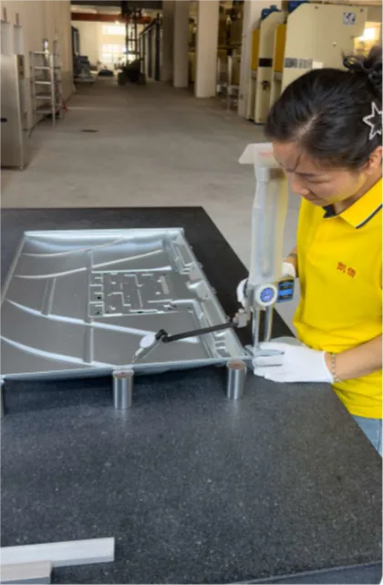
The cover shows an inspection panel in supplied company materials. It does not evidence a specific tolerance, measurement, or qualification. The hypothetical case in section 09 is invented for planning only and is not a customer project, a test result, or a KINGSUN measurement. Every tolerance decision for a real program must be built from the approved drawing, the mating parts, the assembly sequence and the agreed inspection state.